Overview
The Maxmix controller has been designed to be easy and fun to build. It uses a combination of 3D printed parts and off-the-shelf electronic components. All parts can be easily found and ordered online!
The total cost of the parts is ~$25.00 USD including the 3D printing and shipping. It takes around 25 minutes to build.
Let’s get started!
Parts
All parts for the Maxmix controller can be found and purchased online. Links to the parts are provided below but feel free to purchase them elsewhere. When looking for alternatives, just make sure the part specifications match to avoid any issues.
3D Print
The enclosure for the controller is made of a couple of 3D printed parts and can be downloaded from Prusaprinters.org.
If you don’t have a 3D printer, I recommend using a community printing service such as Treatstock, it is the most cost effective method.
Hardware
Below are the rest of parts needed to complete the project.
* Due to DOA reports on Arduinos ordered from AliExpress, we’ve decided to not provide a link.
| Part | Count | AliExpress | Amazon (US) |
|---|---|---|---|
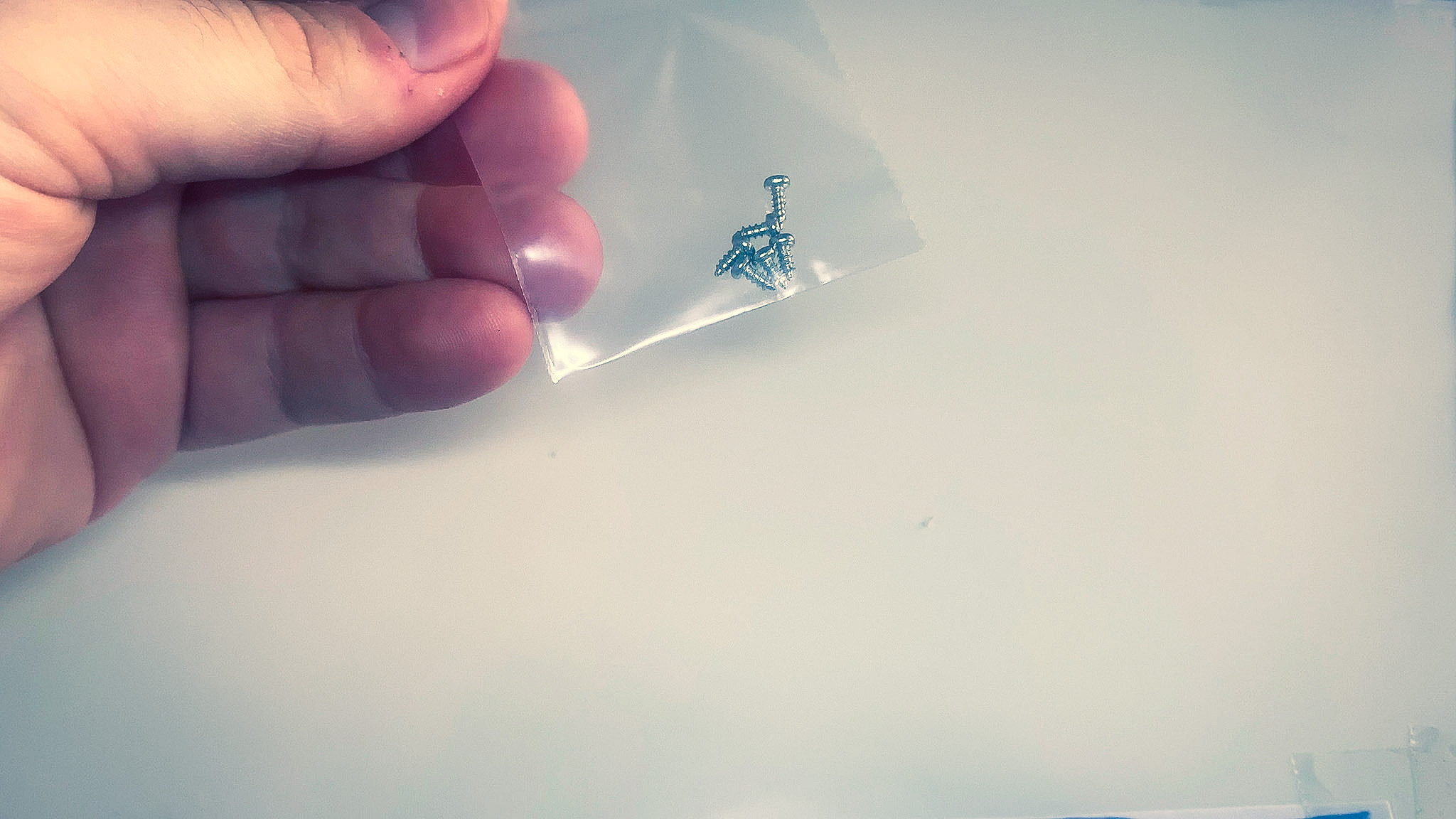
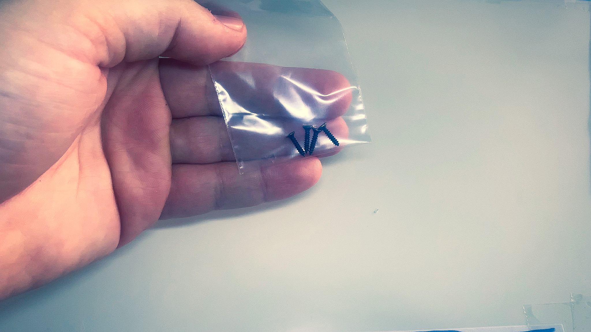
| M2 10mm Countersink screws | 4 | Link | Link |
| M2 5mm Screws | 6 | Link | Link |
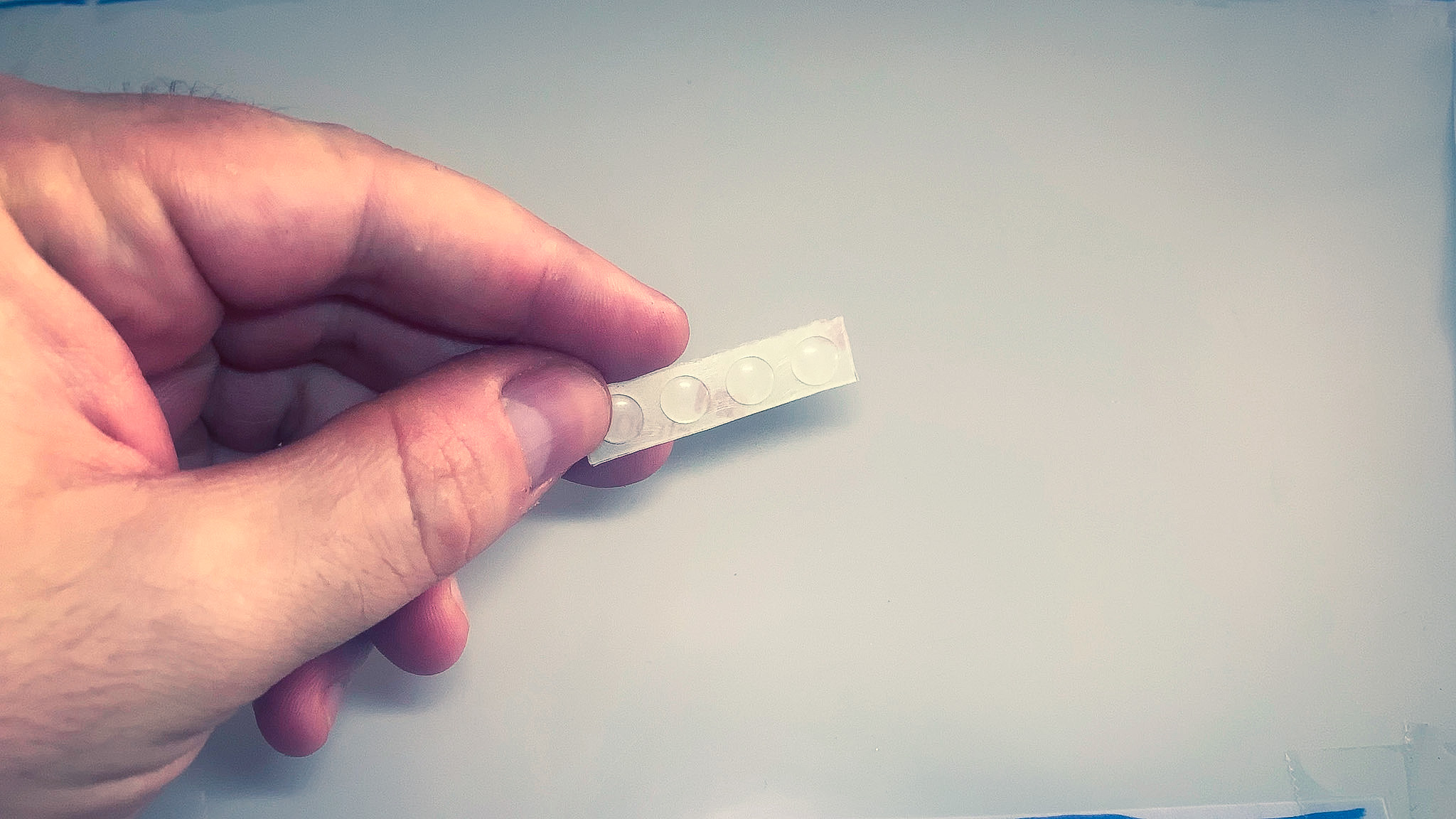
| Silicon bumper 2x8mm | 4 | Link | Link |
| Arduino Nano 328P CH340 | 1 | * | Link |
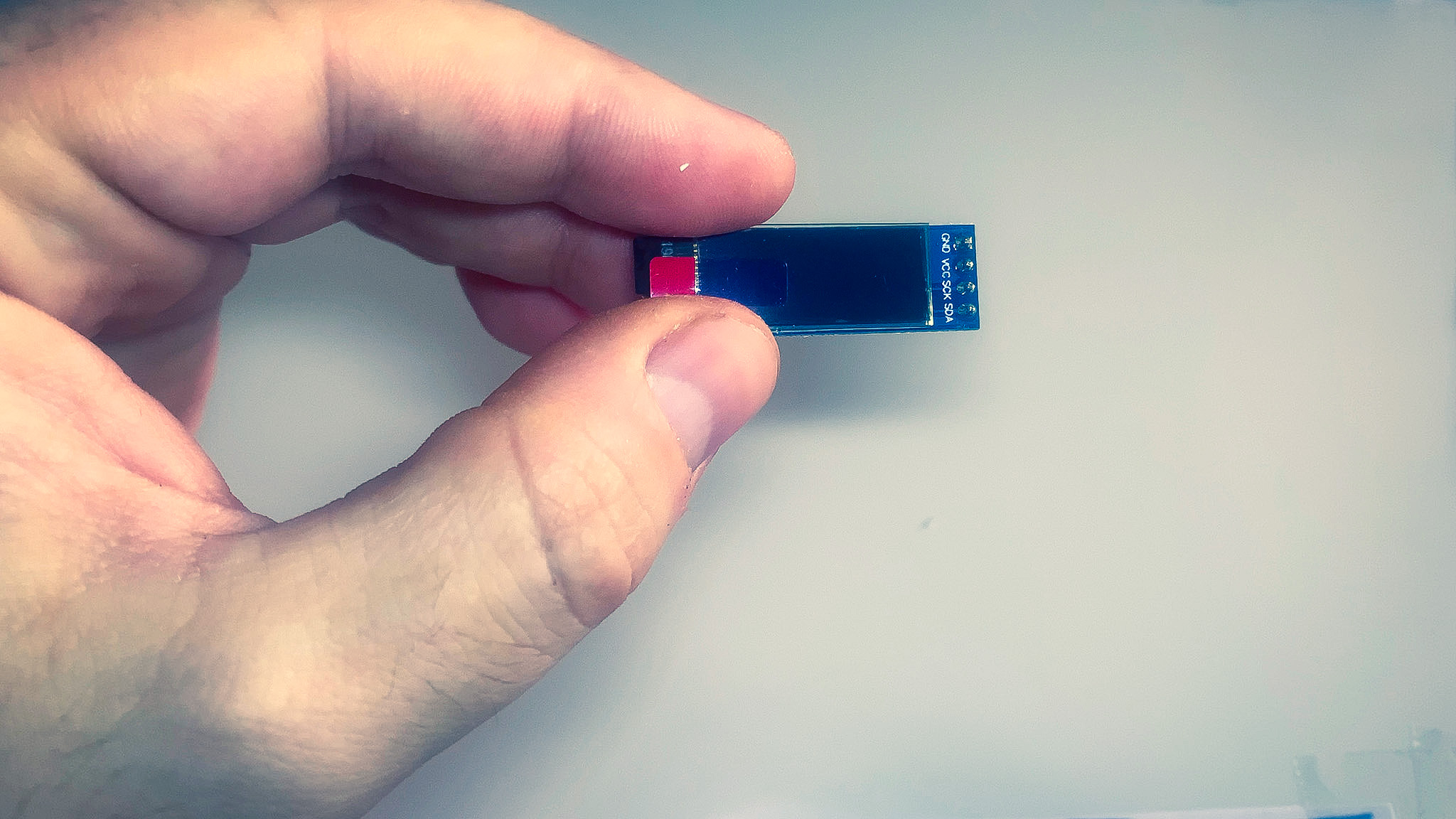
| 128x32 I2C OLED display | 1 | Link | Link |
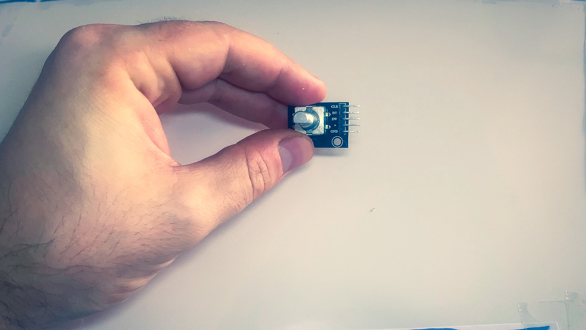
| Rotary encoder | 1 | Link | Link |
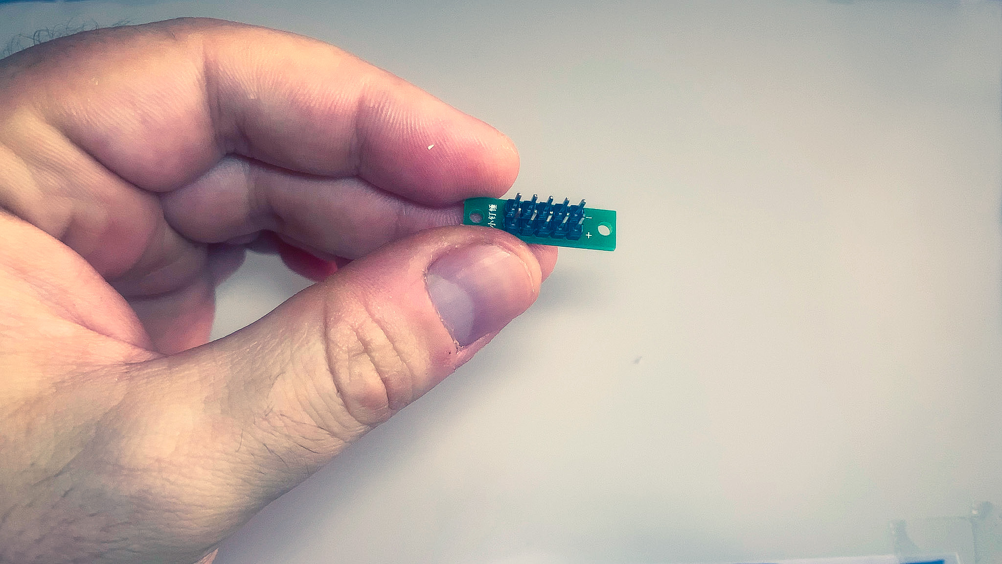
| Power bus | 1 | Link | Link (Tindie) |
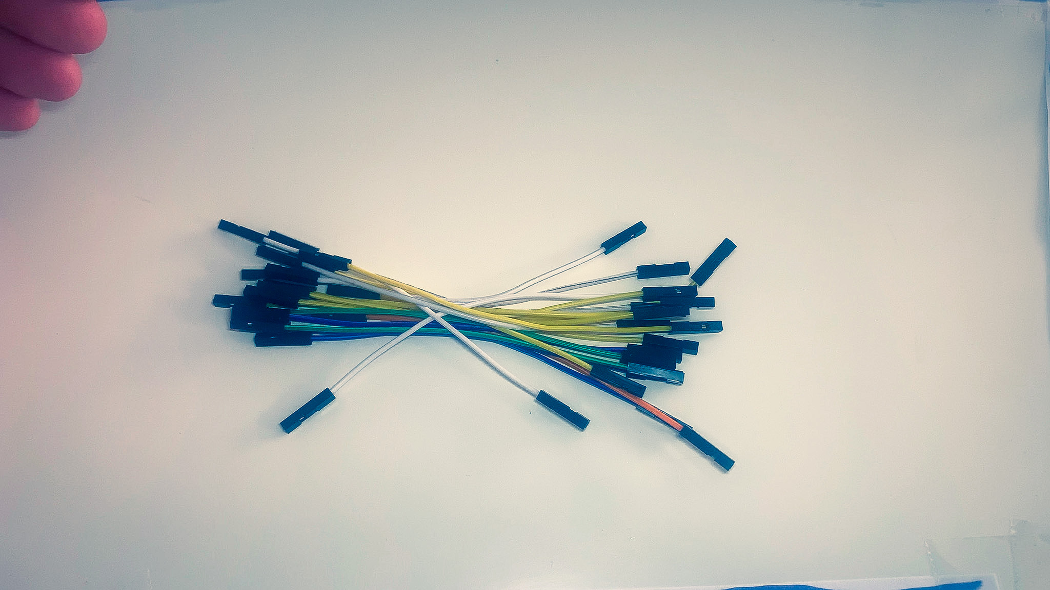
| 10cm Female to female jumper wires | 11 | Link | Link |
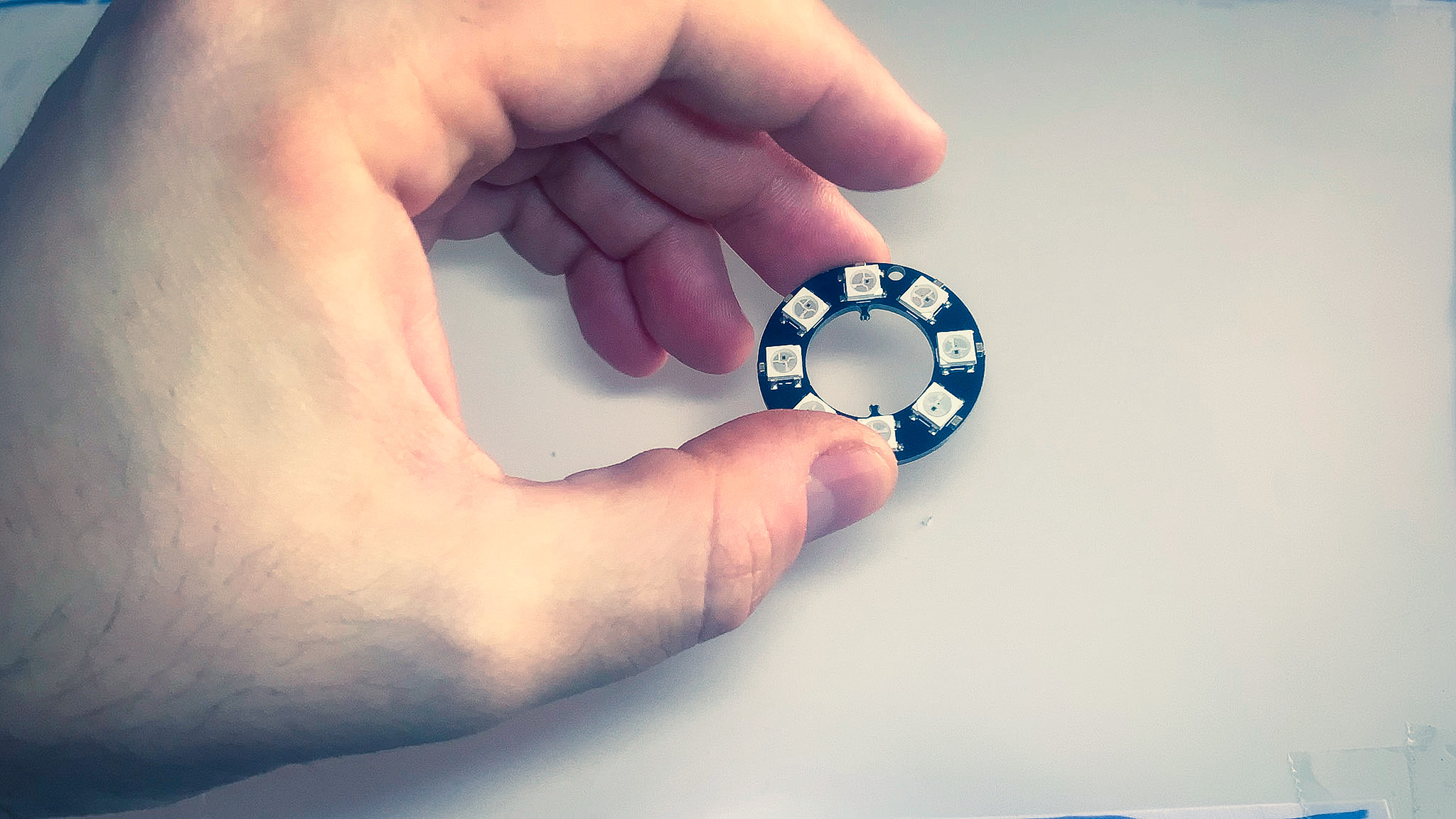
| WS2812 5050 LED Ring 8-bit (Optional) | 1 | Link | Link |
| Conductive Glue (Optional) | 1 | Link | Link |
Tools
Here are the tools you are going to need.
- Small philips screwdriver
- Soldering iron (or alternative such as conductive silver epoxy)
- Needle nose pliers
- Wire cutting pliers
- Wire stripper (Optional)
- Third hand (Optional)
Soldering
Soldering has been kept down to a minimum but some is required. If you are unable to solder, you can try alternative methods such as conductive glue: AliExpress, Amazon
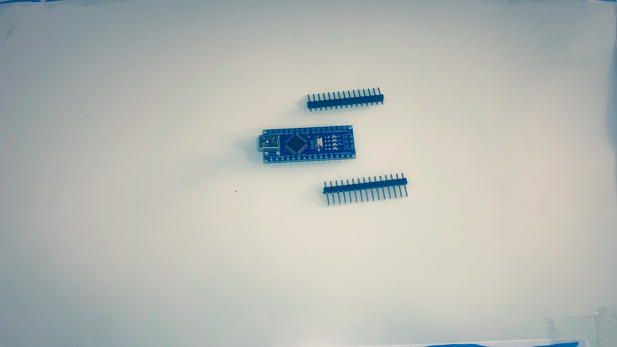
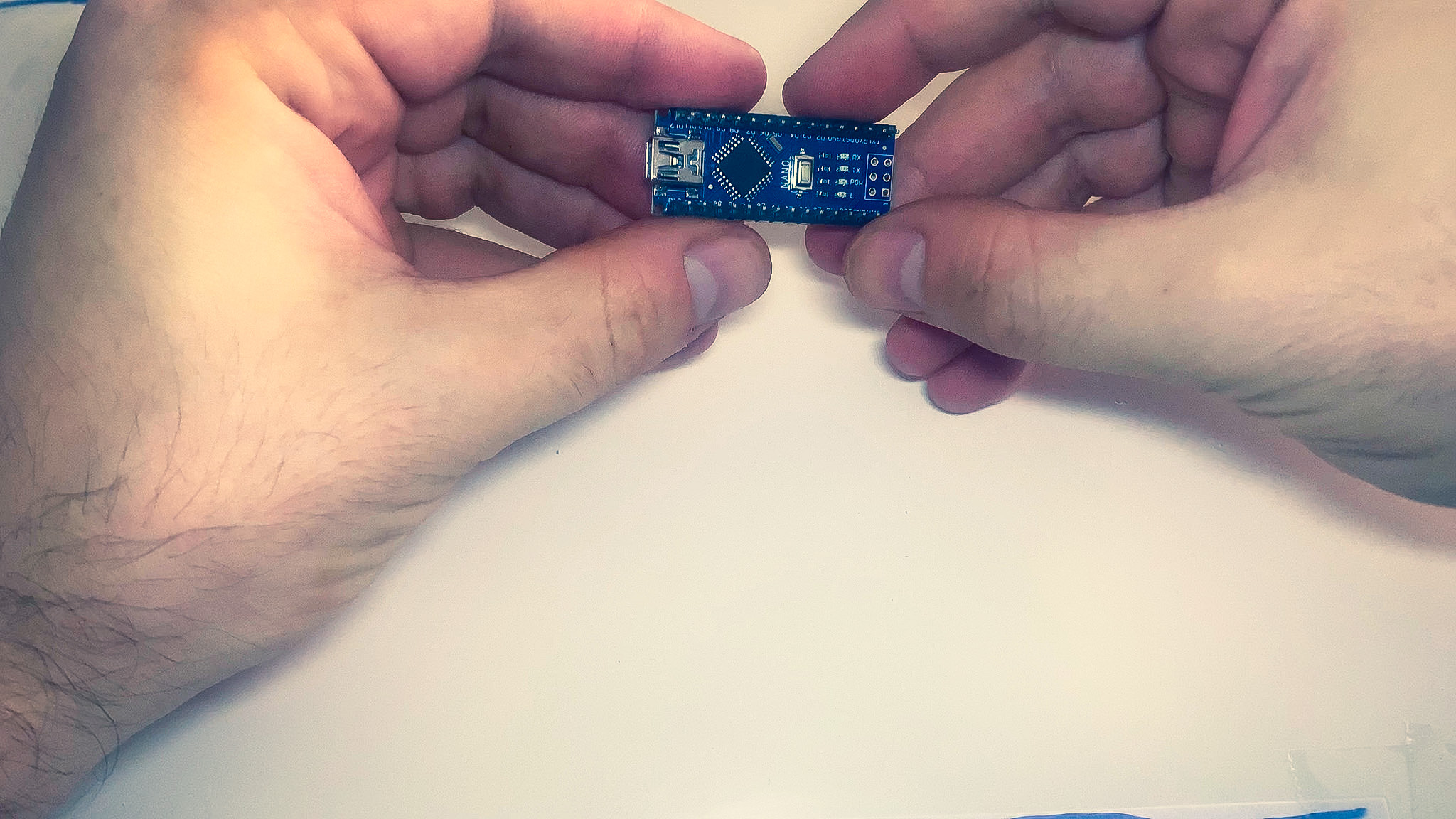
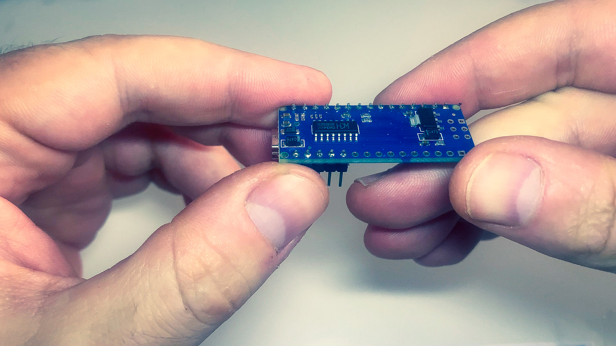
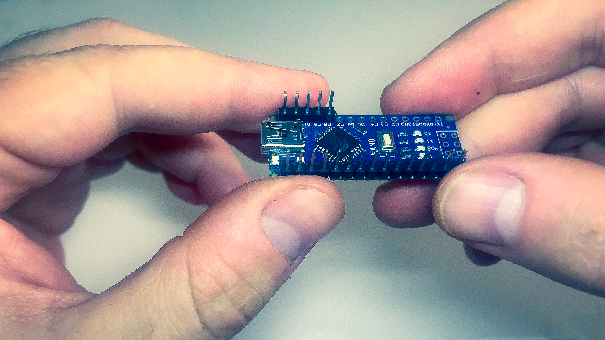
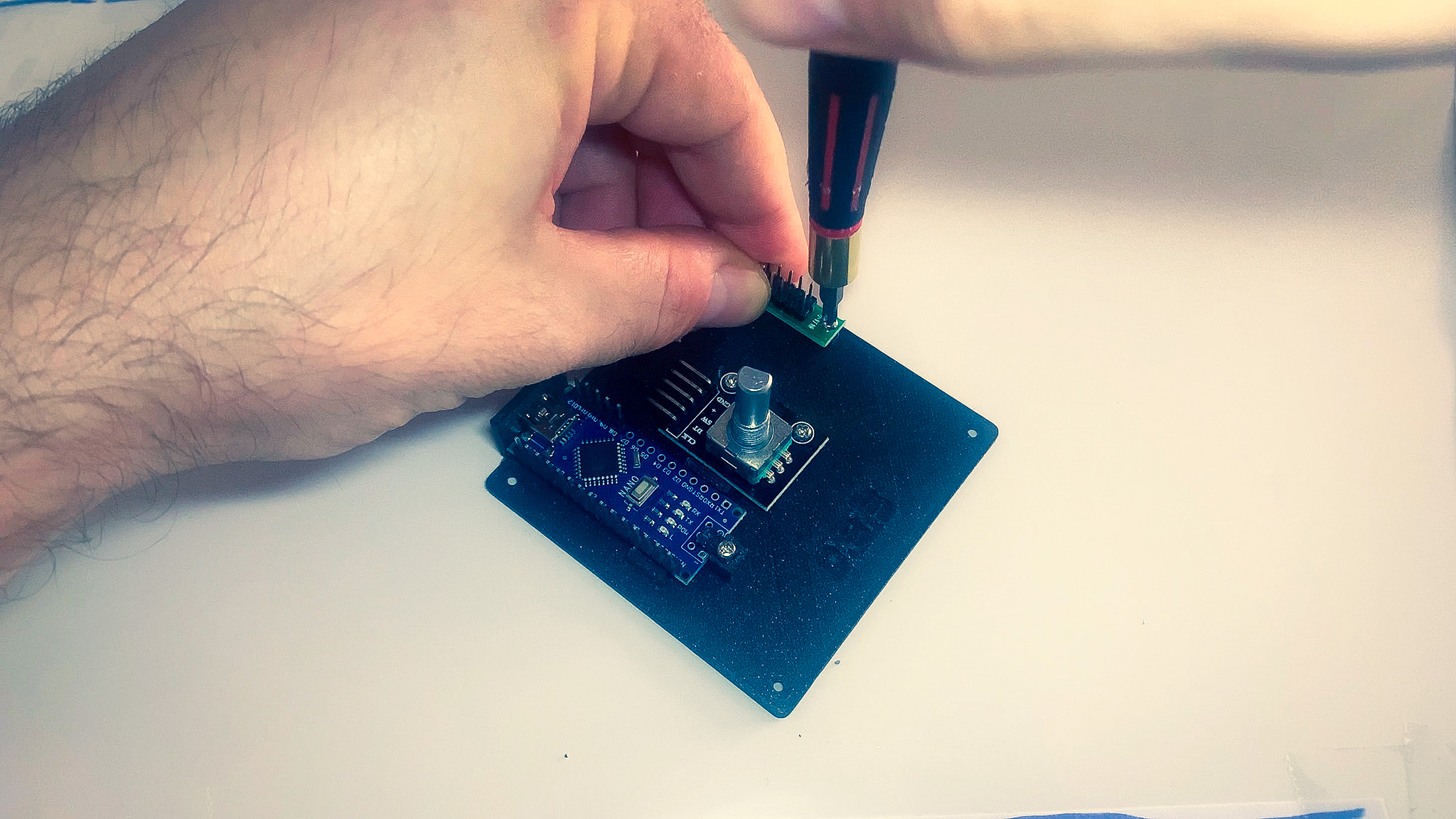
MCU
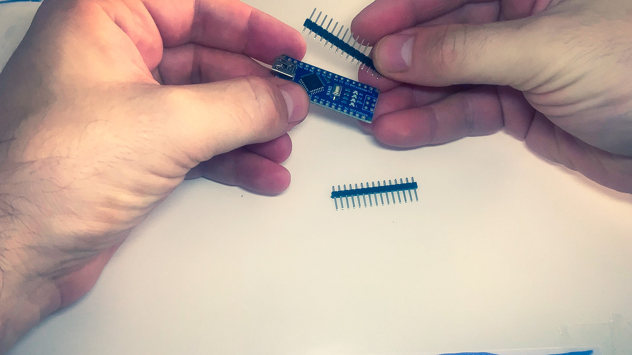
- Locate the side that has pins D13 through VIN.
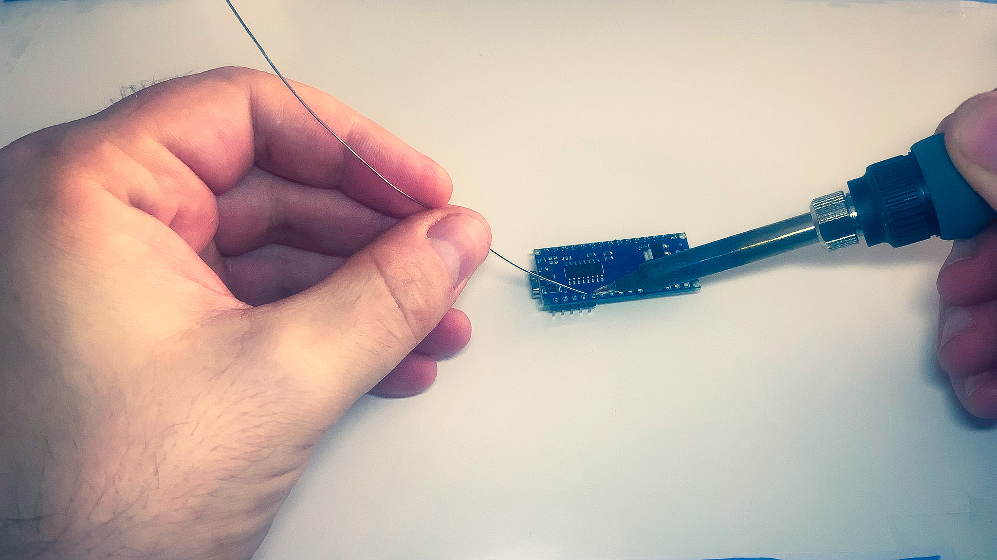
- Insert a row of pins them from the top so shorter ends are poking through the back.
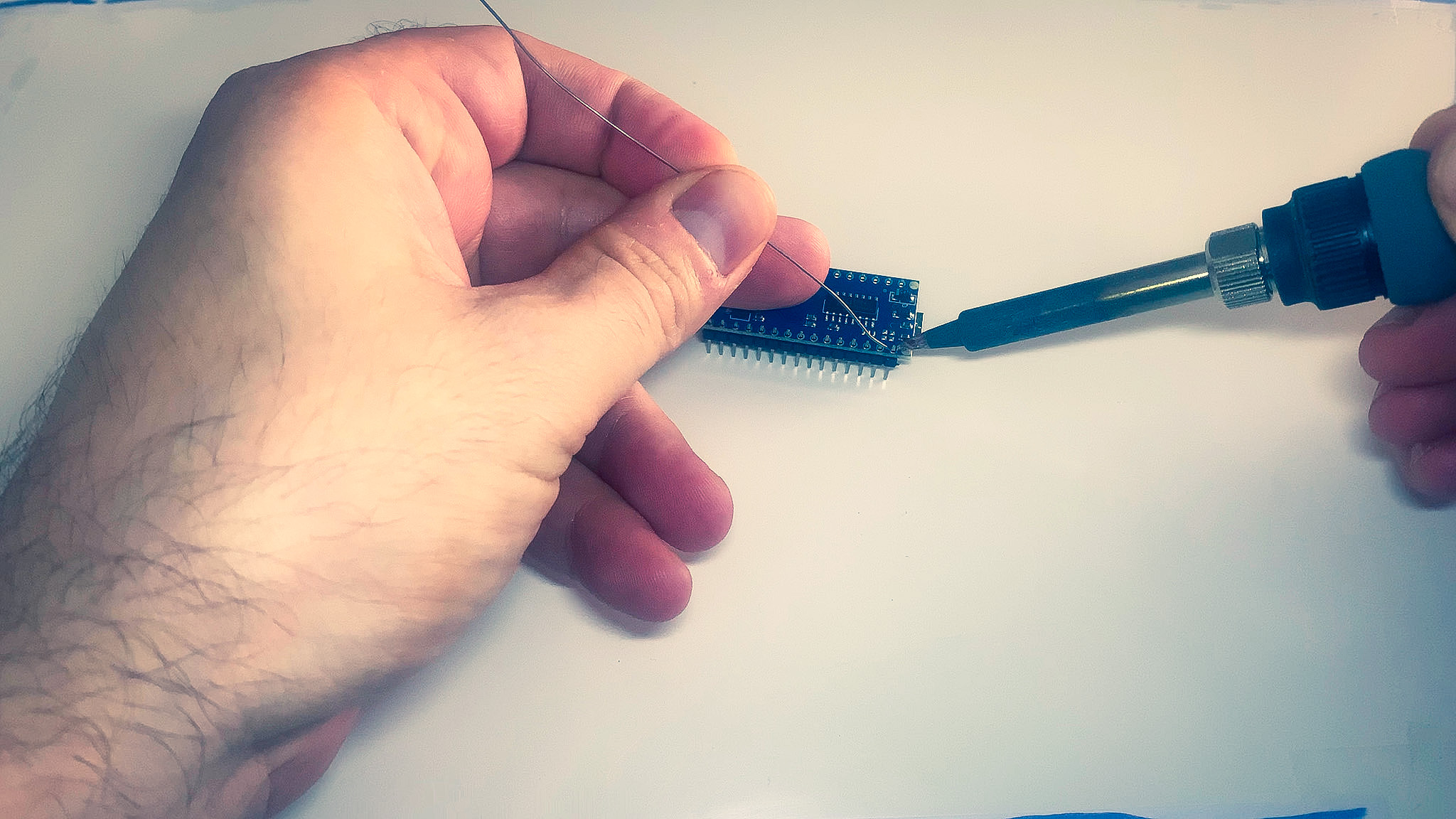
- Solder the pins from below.
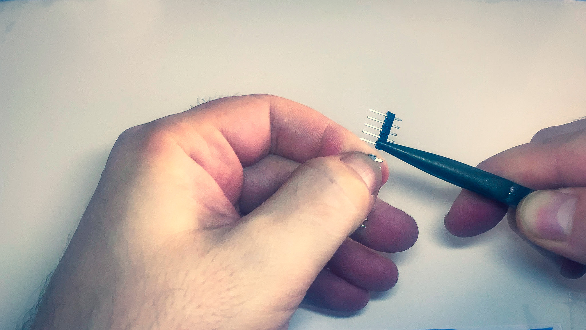
- Use the needle nose pliers top break apart 5 pins from the remaining row.
- Insert them in the MCU between pins D12 and D8.
- Solder them from below.
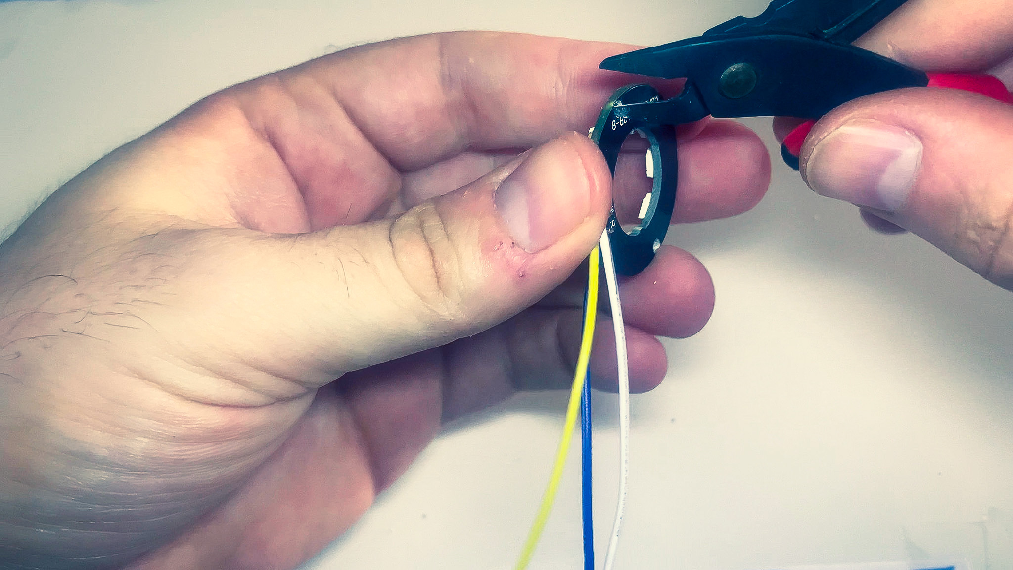
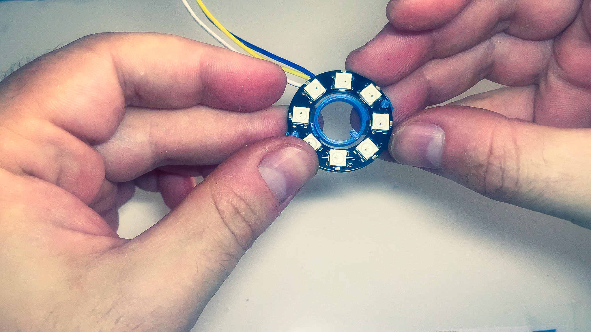
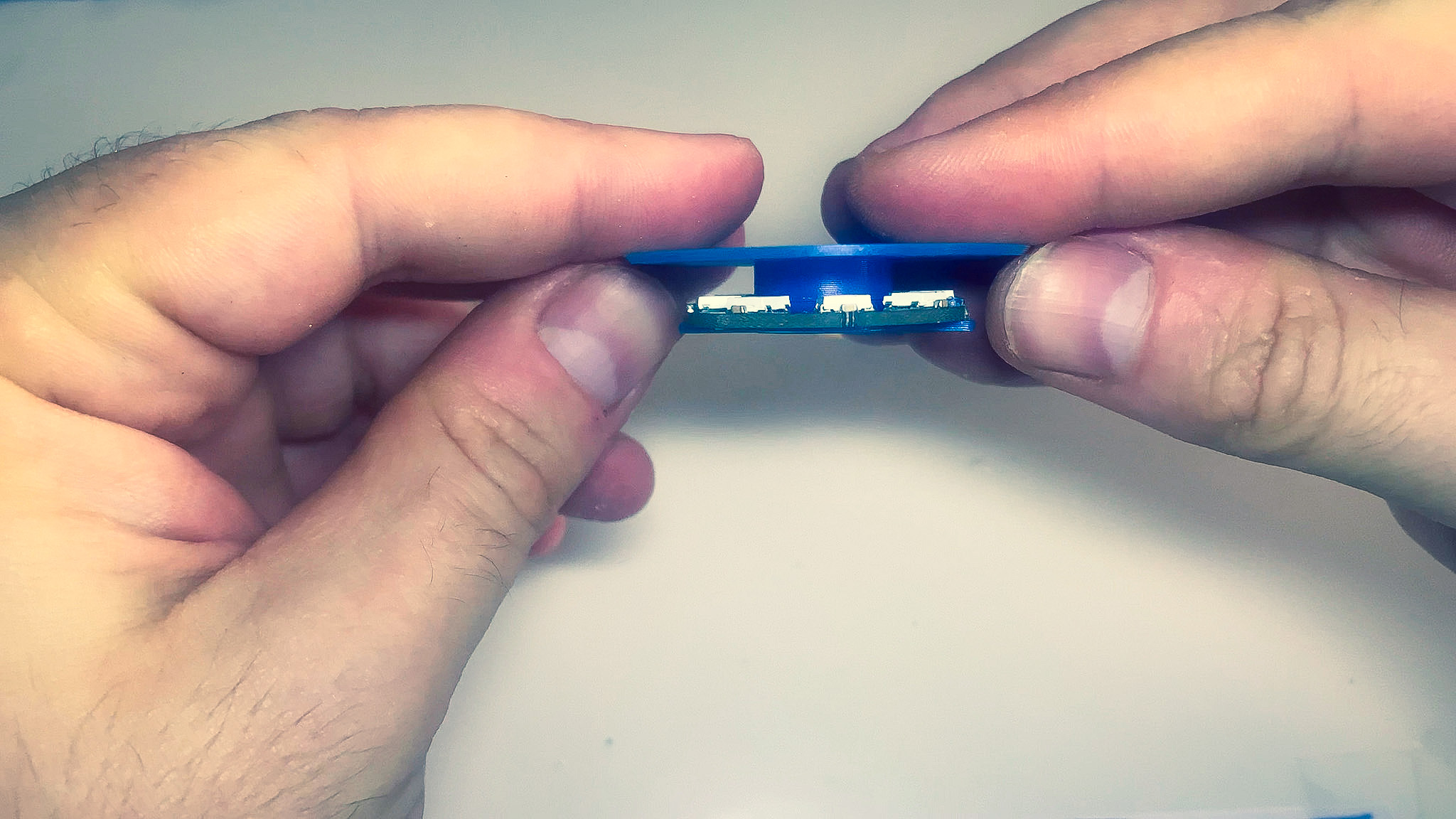
LED Ring (Optional)
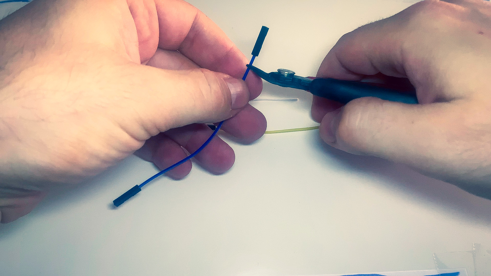
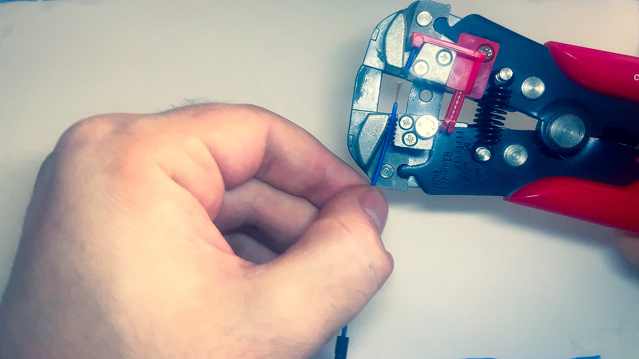
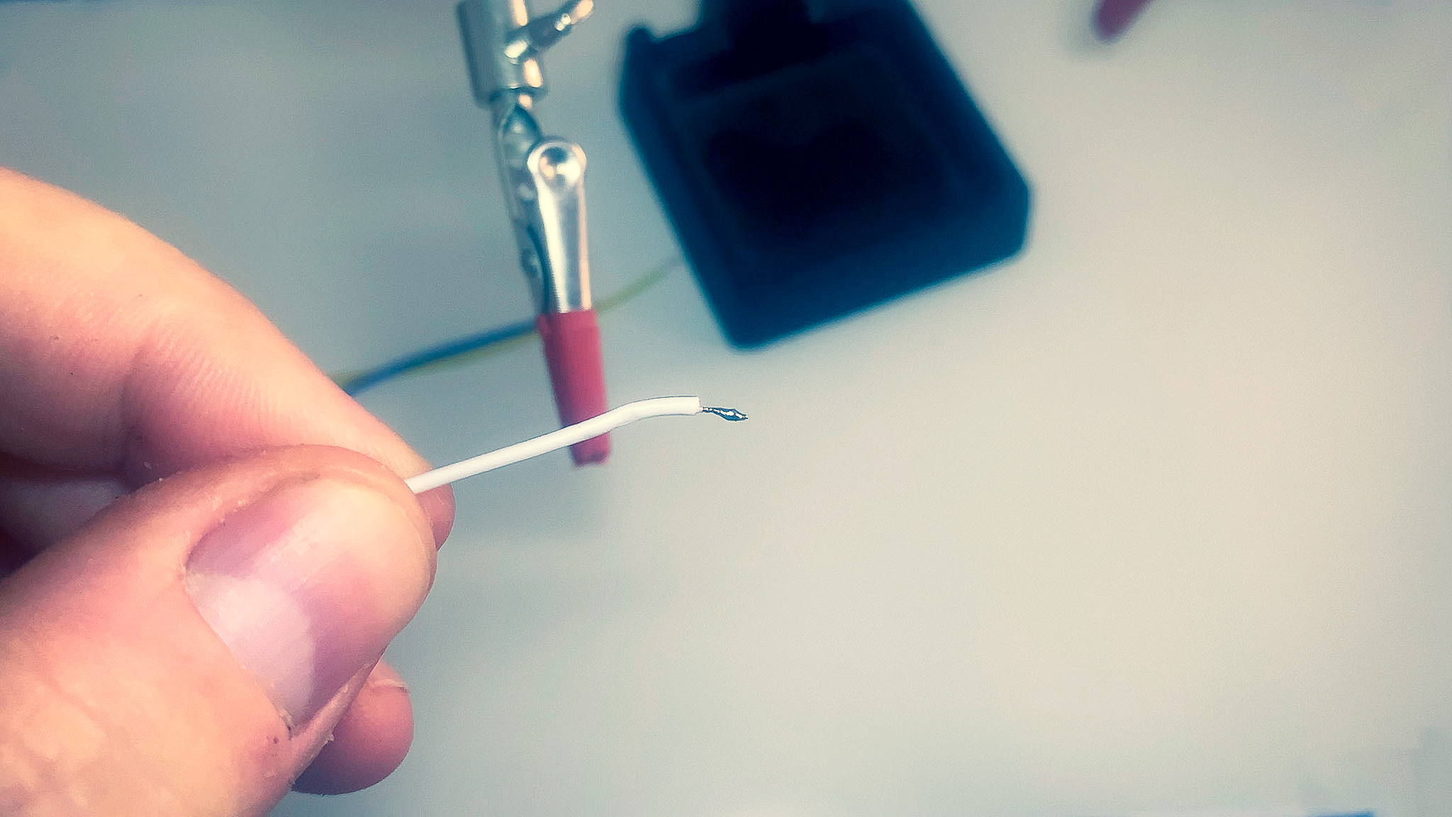
- Grab 3 of the jumper wires.
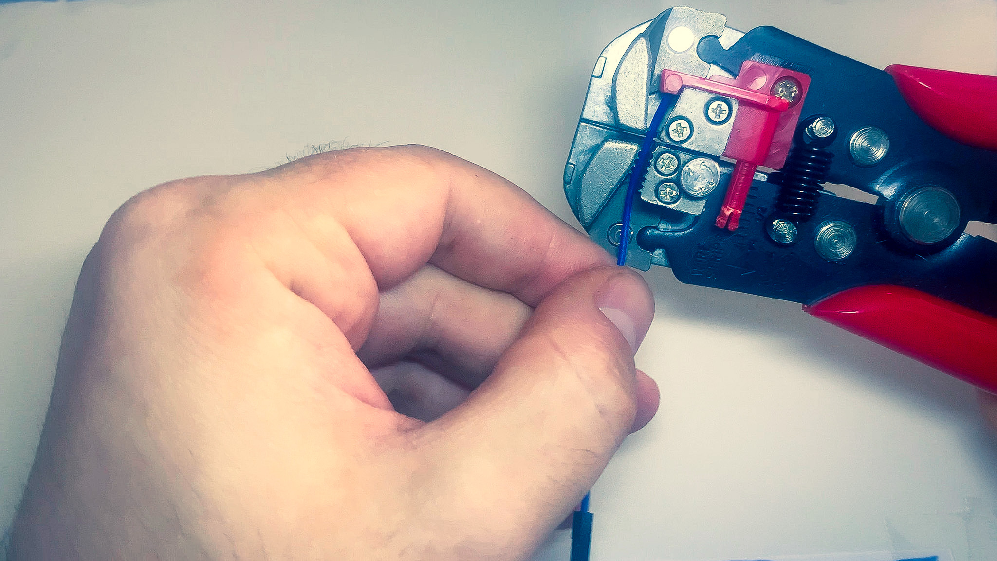
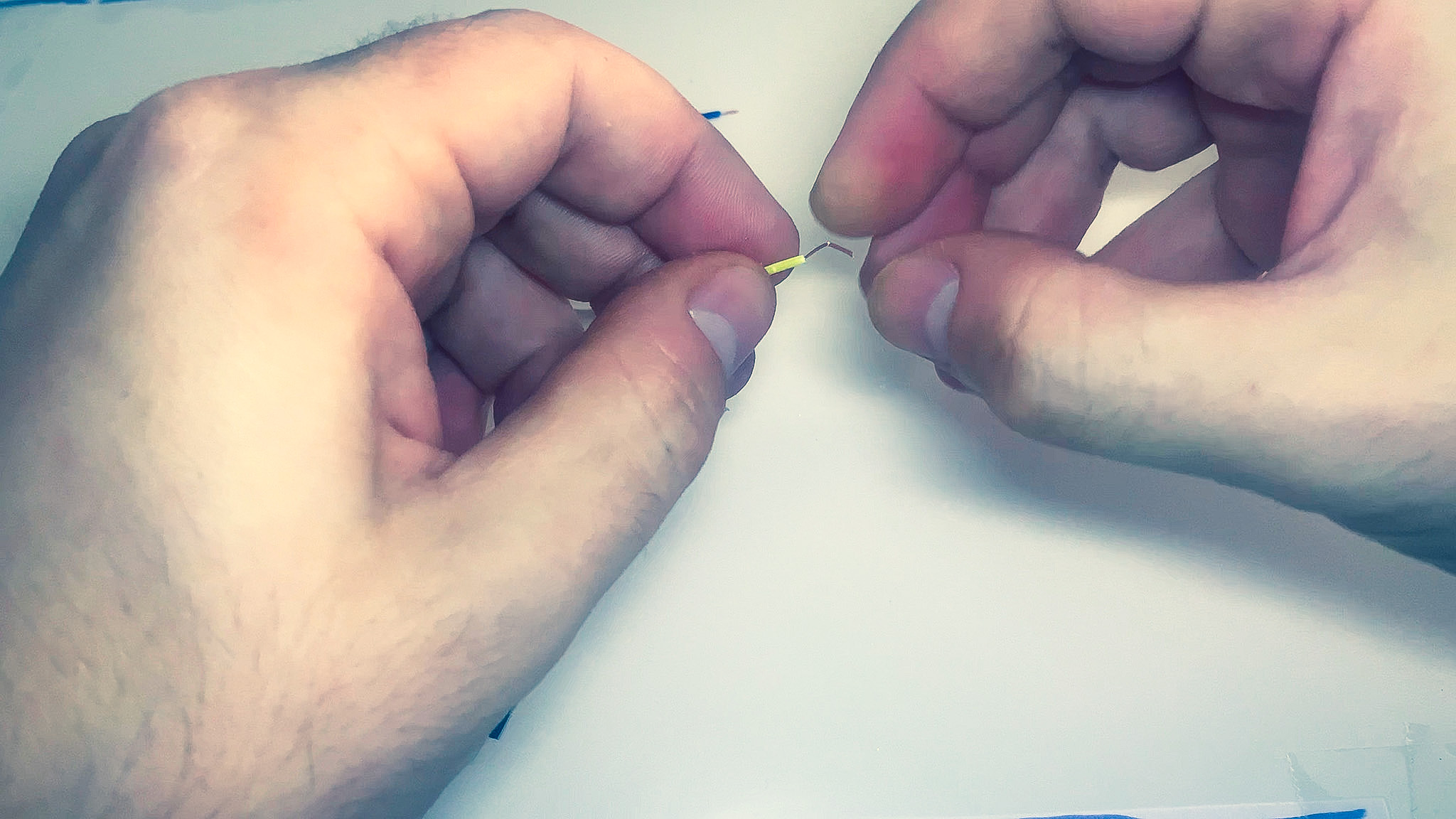
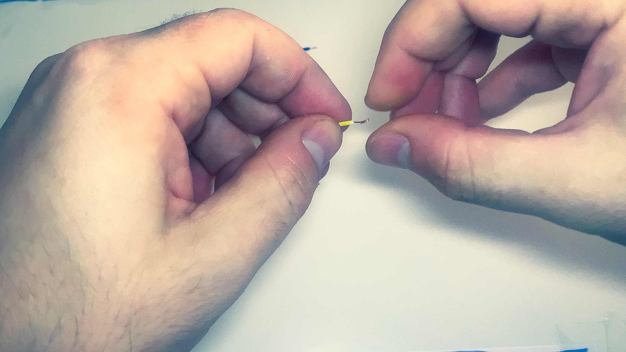
- Using the wire cutters, cut the connectors from one end and strip the wires.
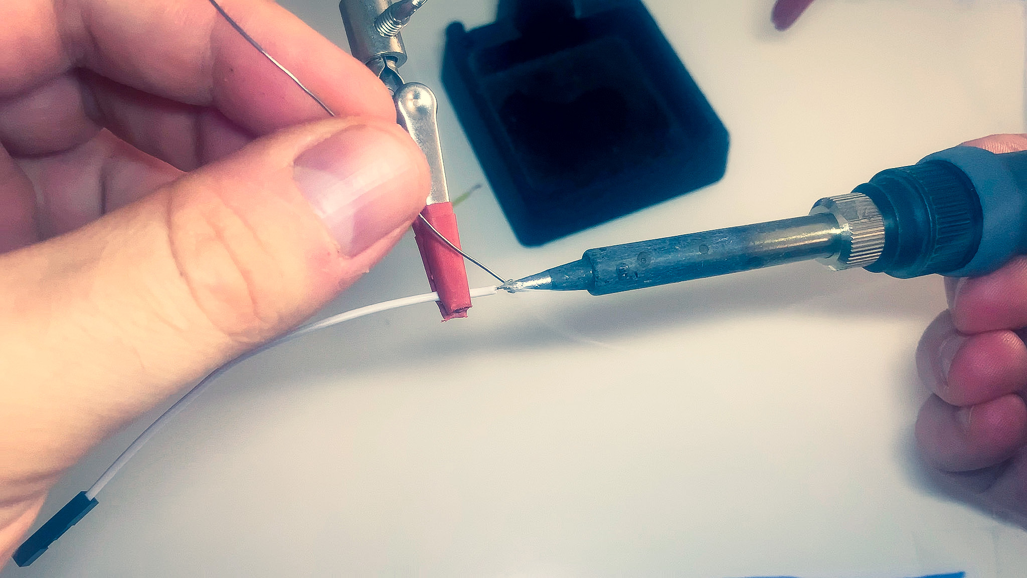
- Use the soldering iron to tin the stripped ends.
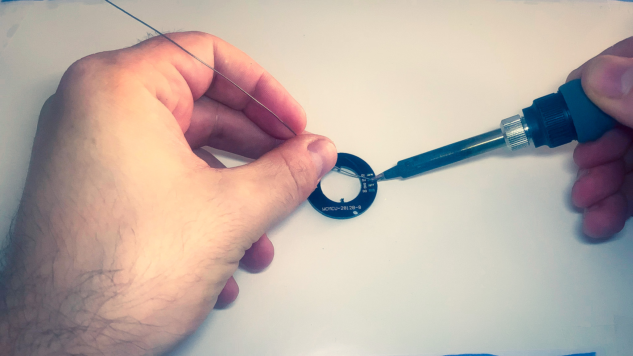
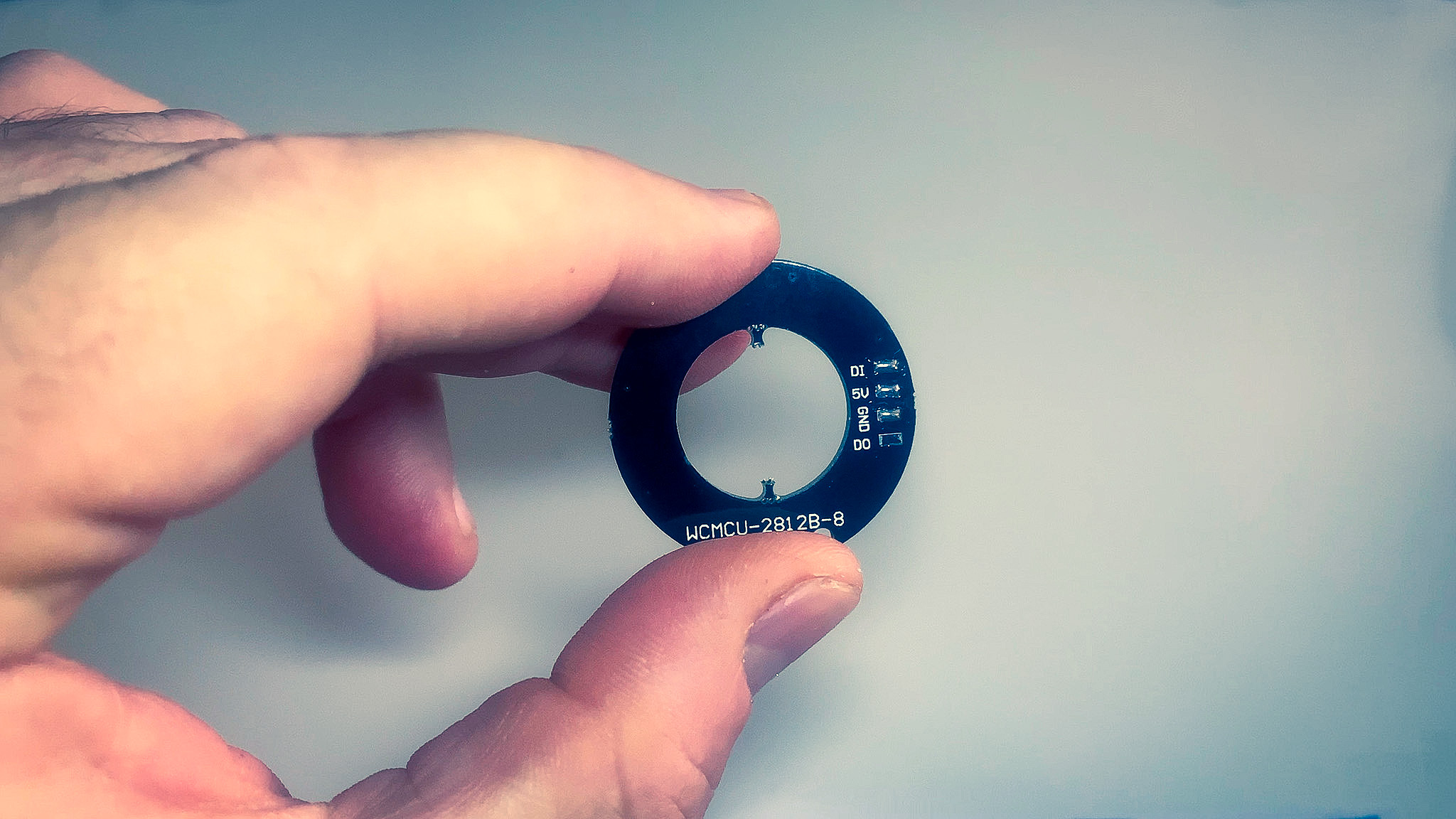
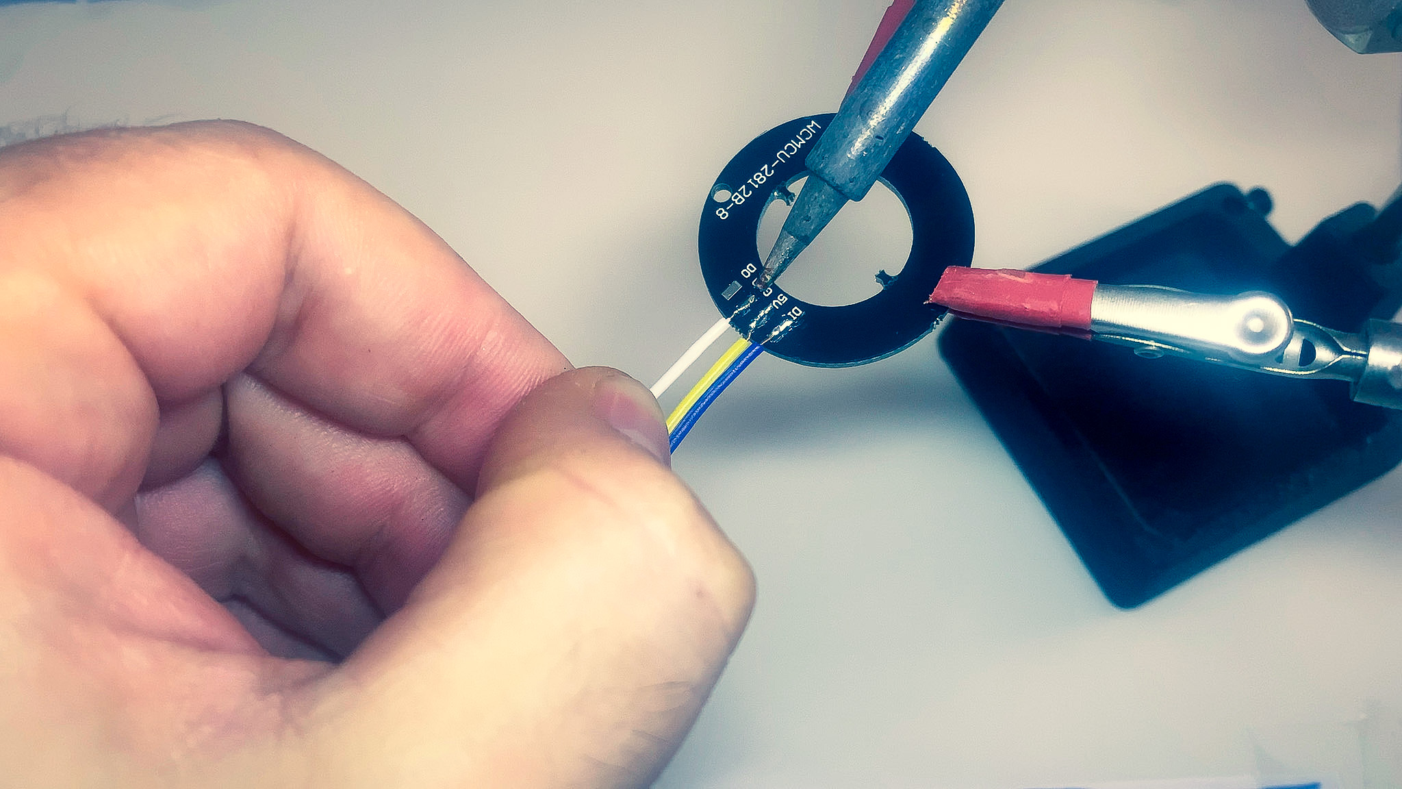
- Tin the pcb connections of the LED ring labeled DI, 5V and GND.
- Solder the wires to the pcb.
Electronics
Grab all the electronic components, the M2x5mm screws and a small philips head screw-driver.
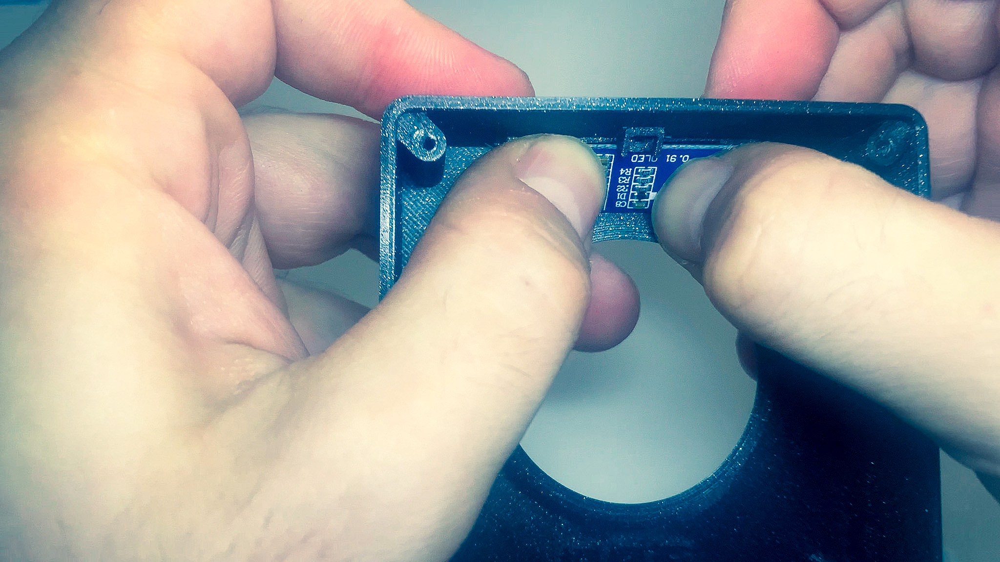
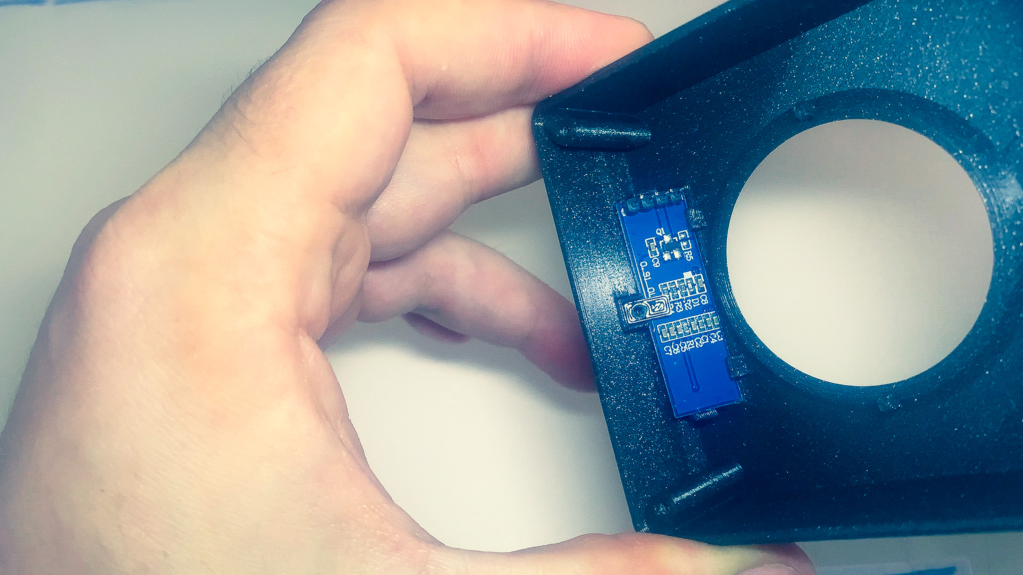
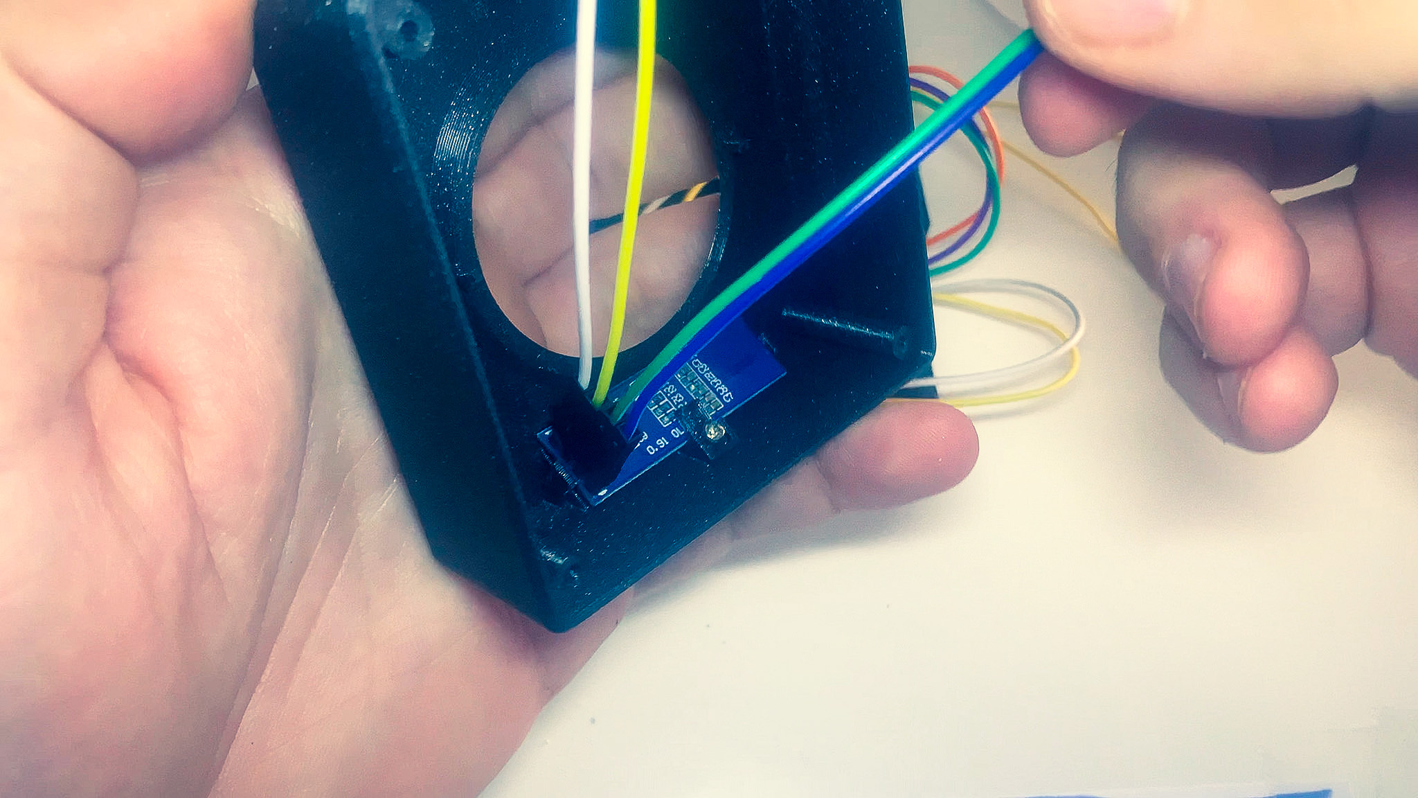
1. Display
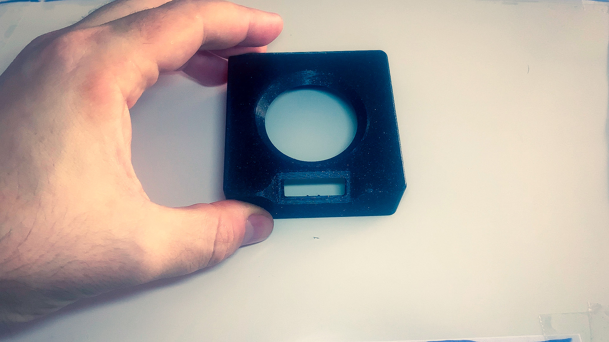
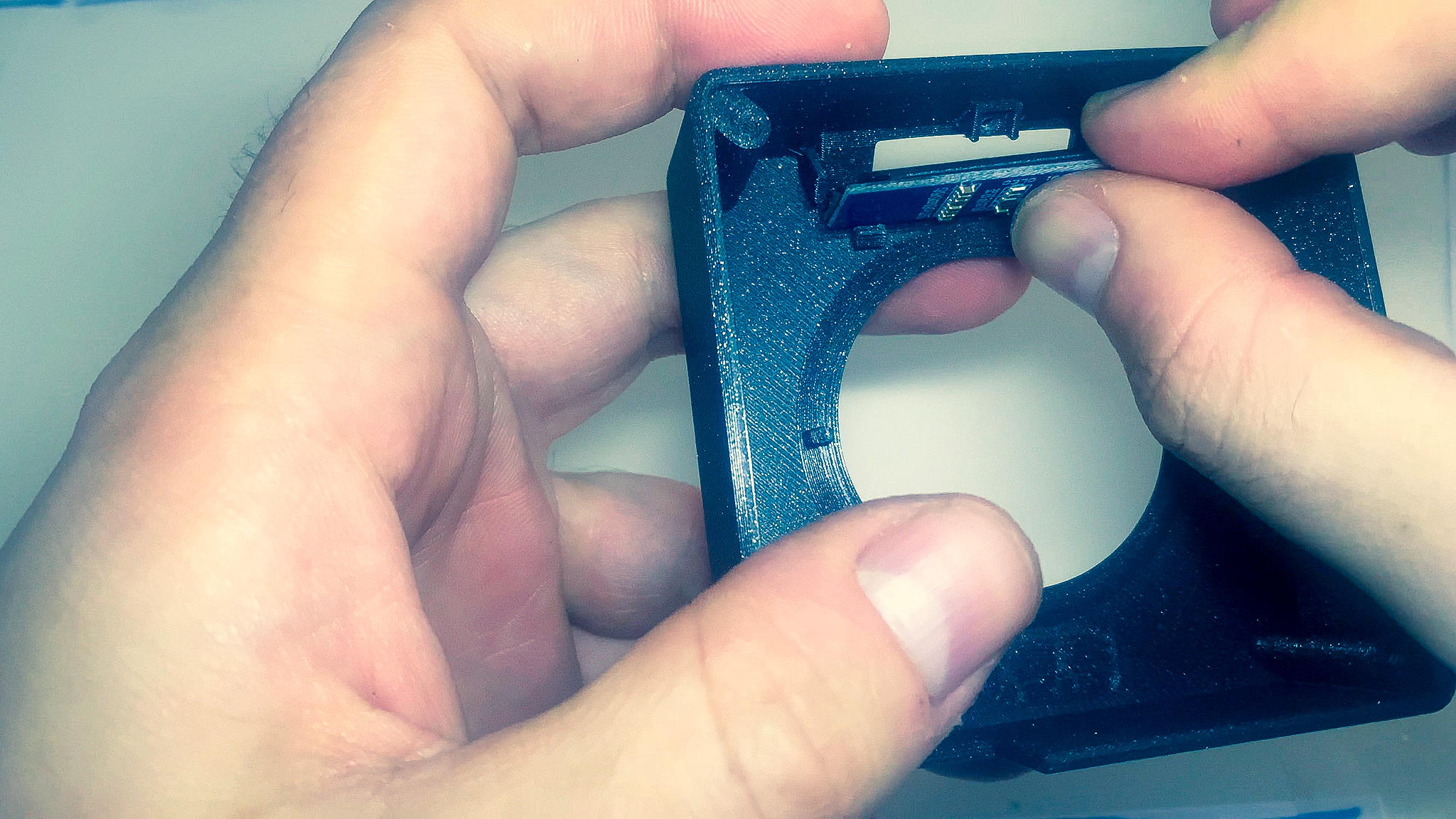
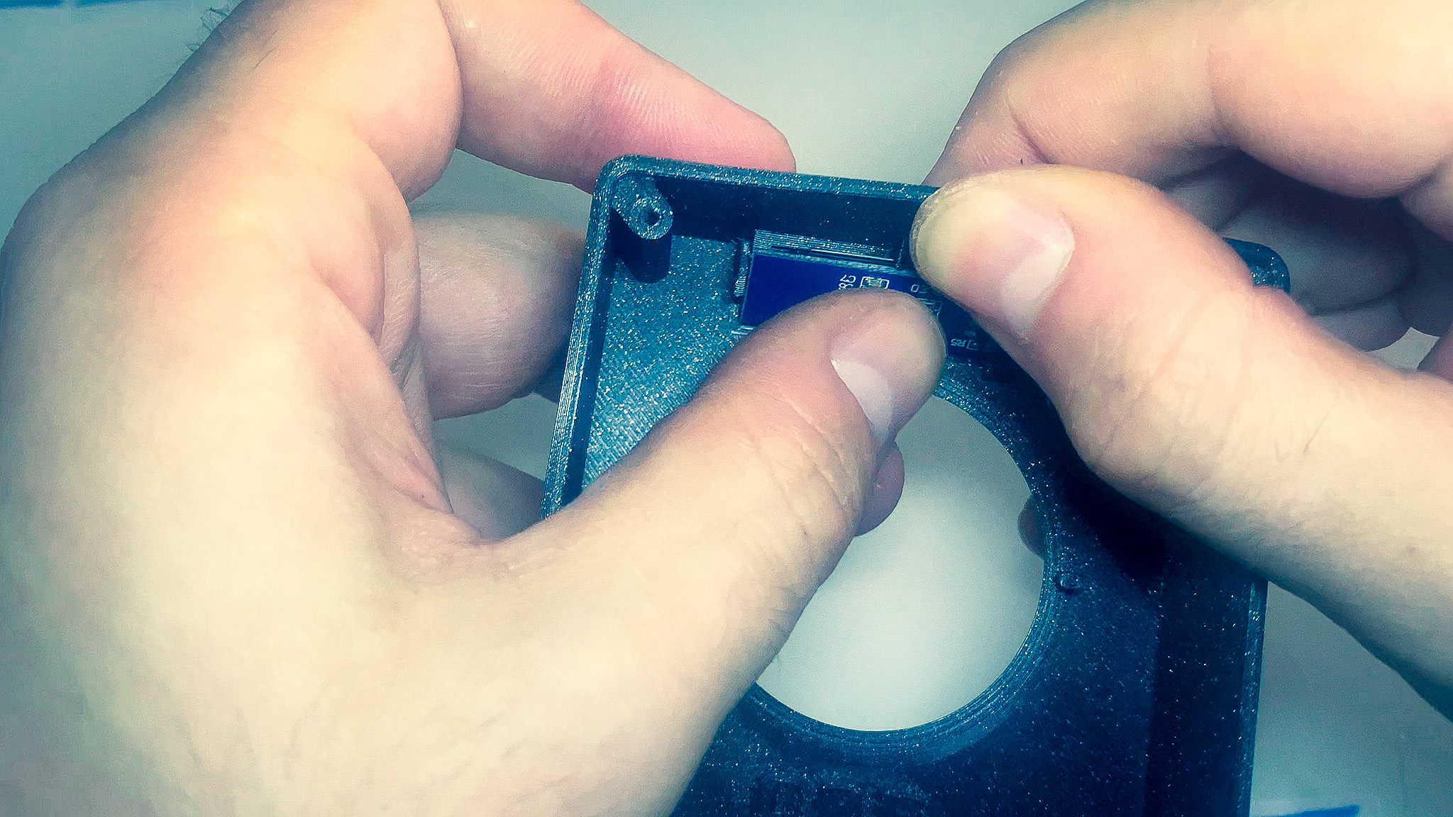
- Grab the OLED display and the top part of the enclosure.
- Insert the bottom of the display first and then push on the top until it is secured in place. If needed, push on the the front wall of the enclosure to help the display slide in.
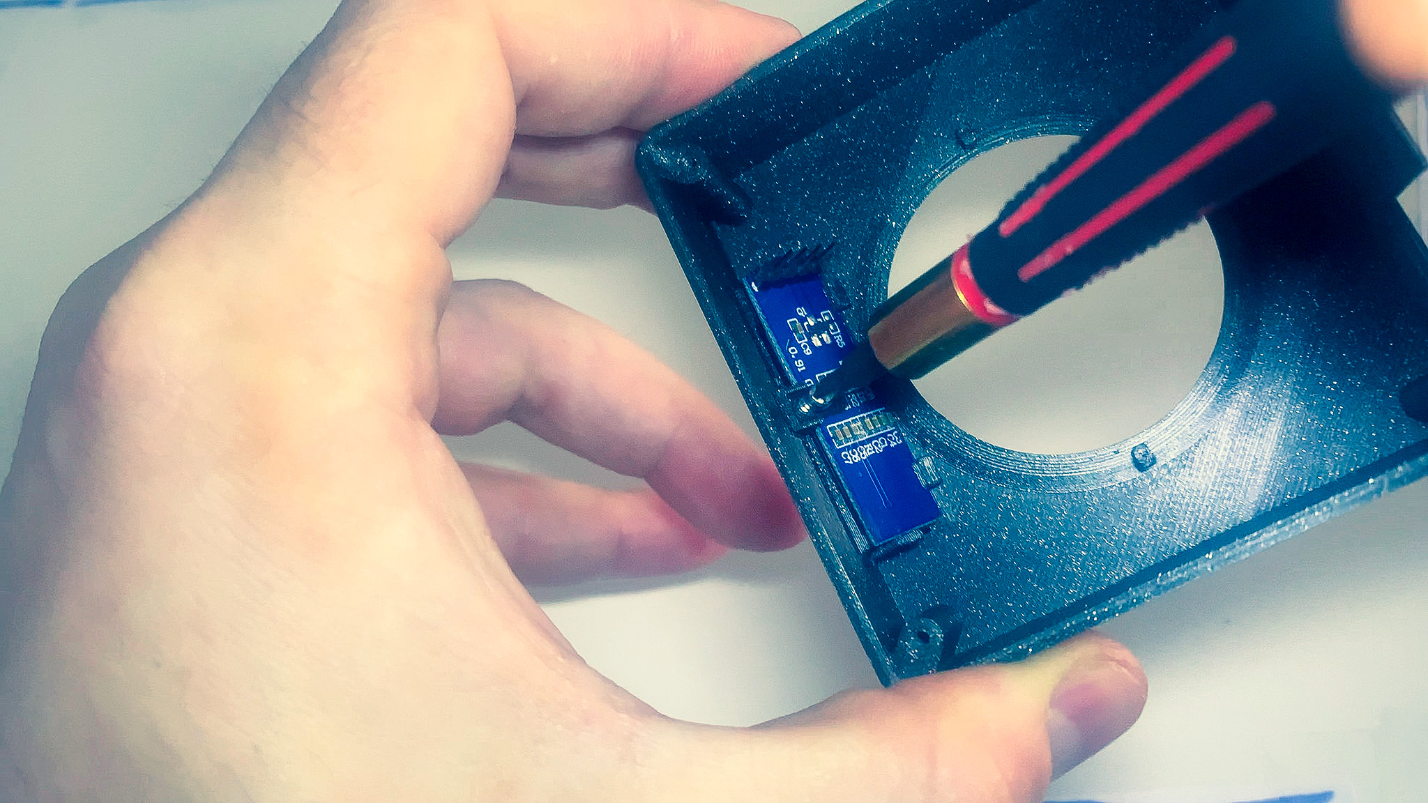
- Drop the P-shaped tab in place and secure it with the screw.
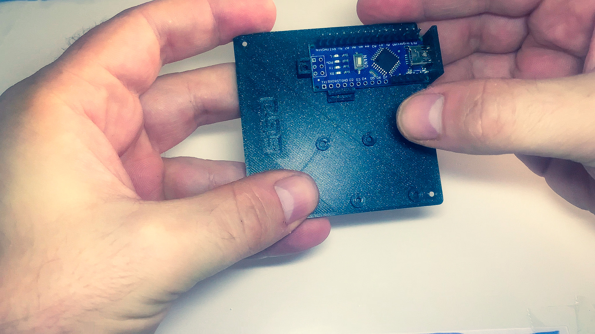
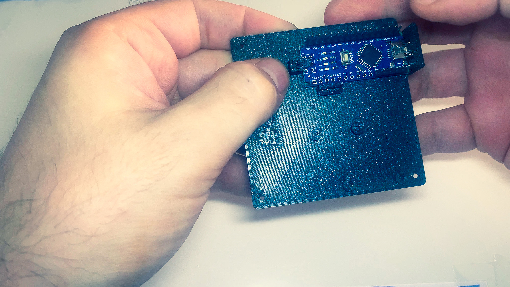
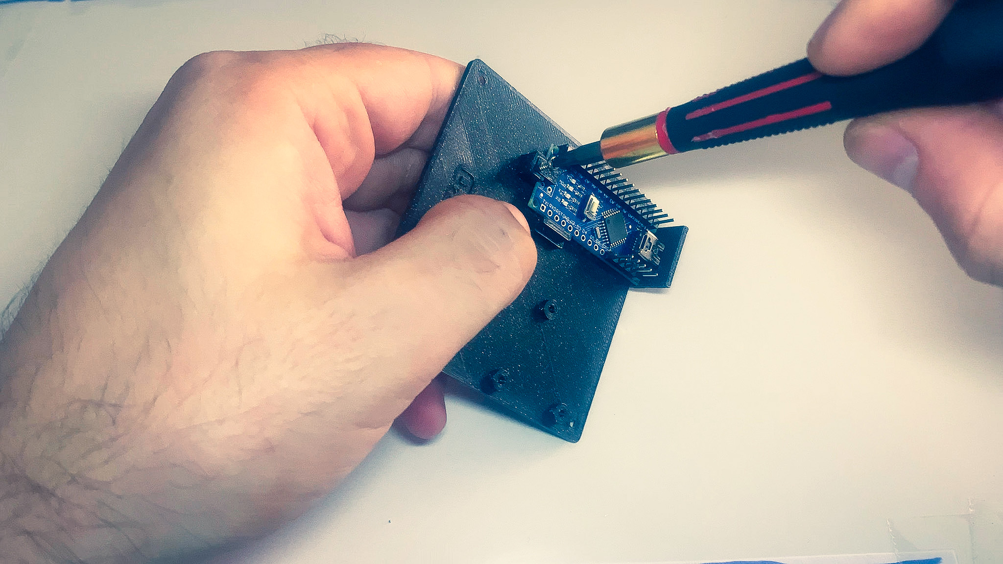
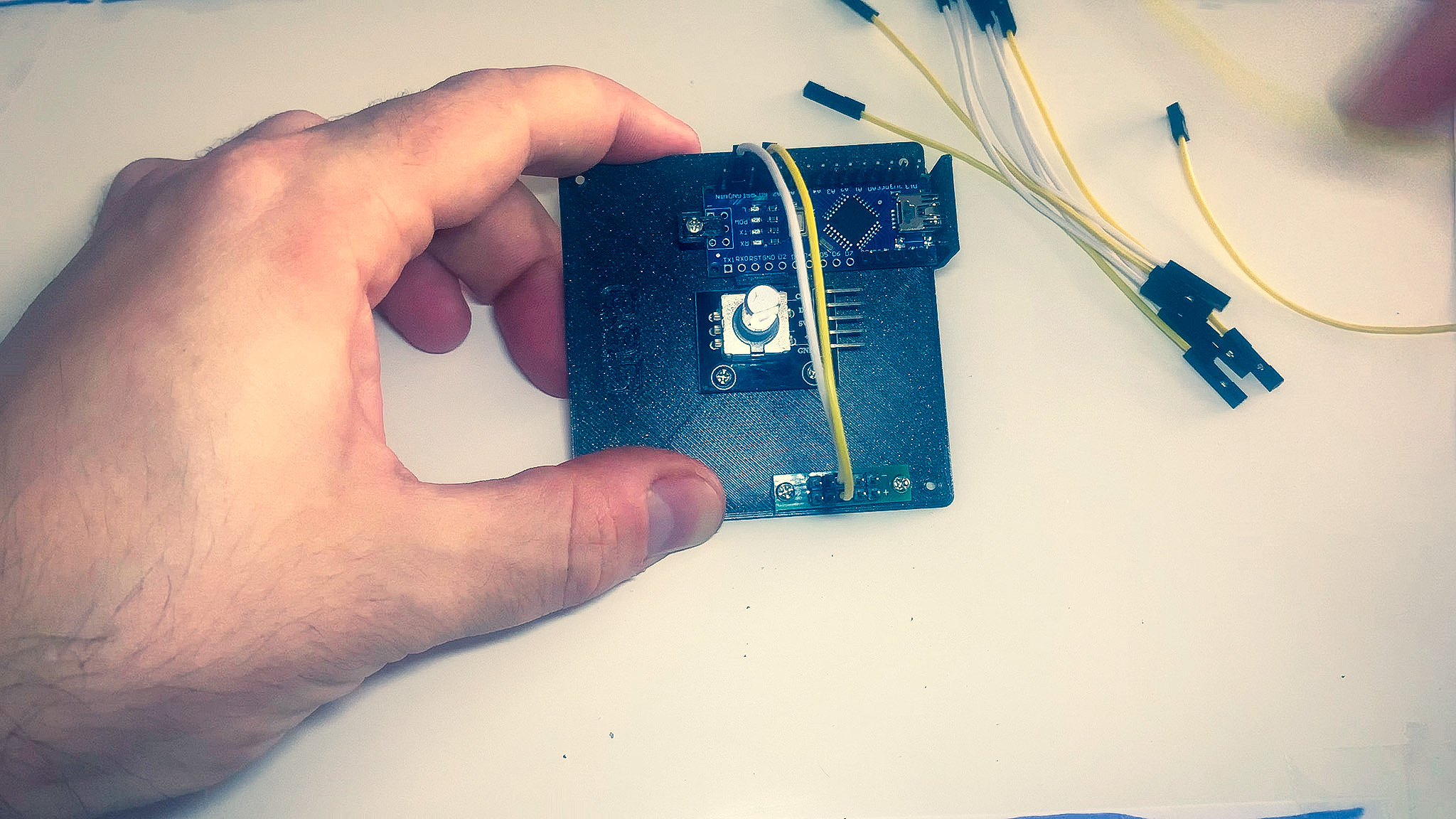
2. MCU
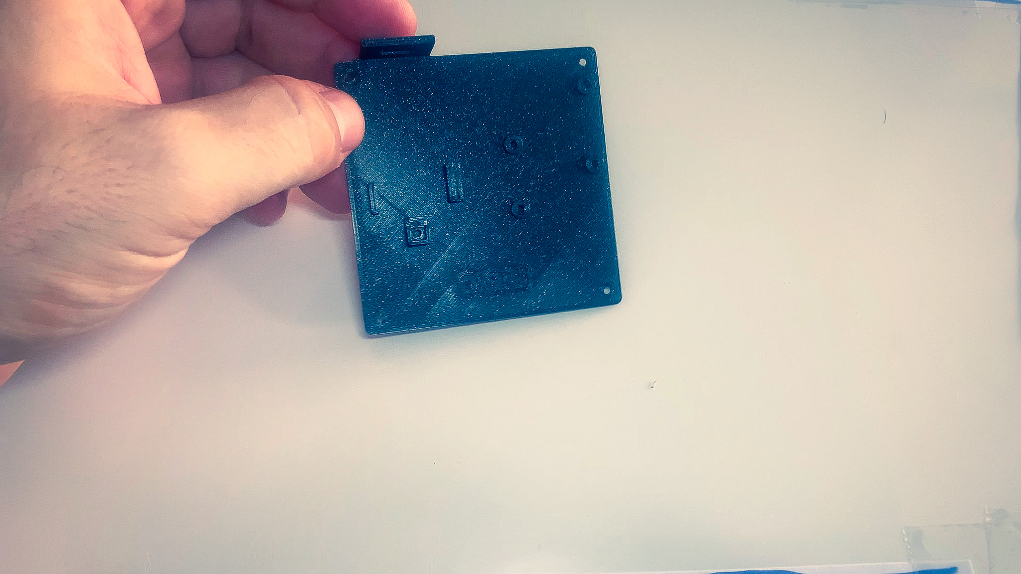
- Grab the MCU and bottom part of the enclosure.
- Insert the USB connector of the MCU into the opening at the back of the enclosure.
- Drop the flat tab in place and secure it with a screw.
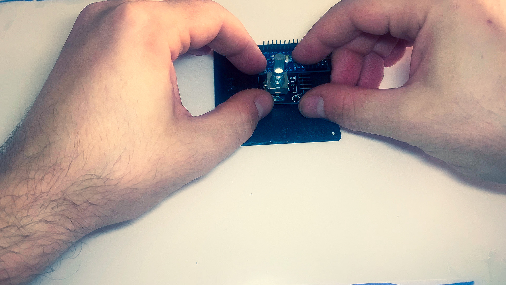
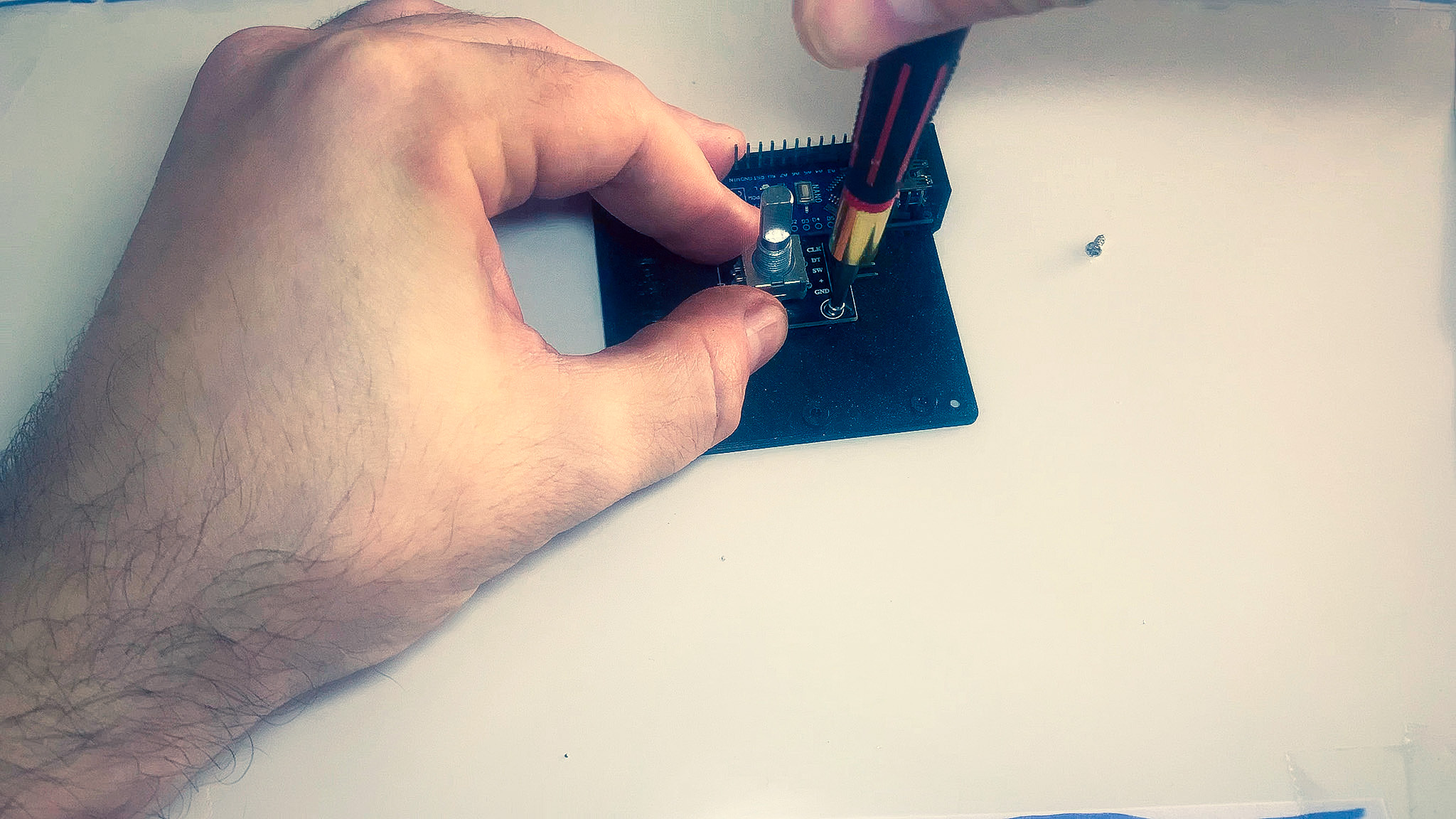
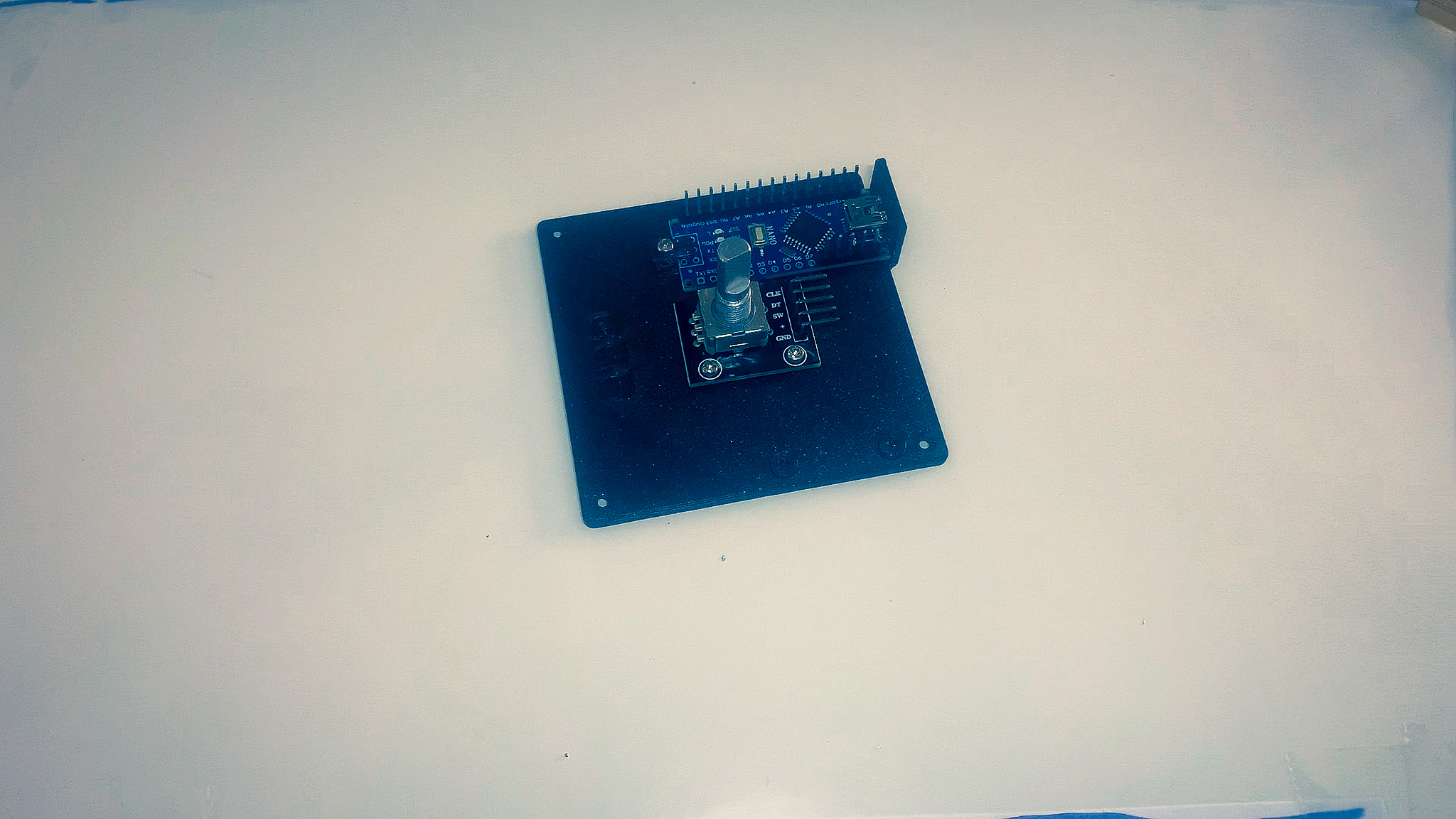
3. Rotary encoder
- Grab the rotary encoder and bottom part of the enclosure.
- Place the encoder in the center, lining up the holes.
- Secure it using the 2 screws.
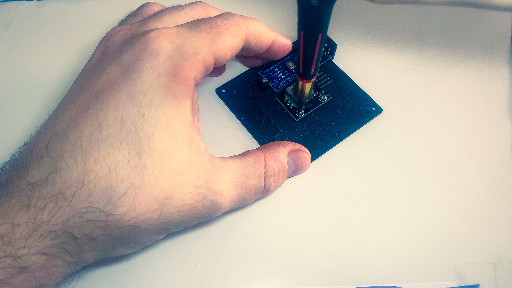
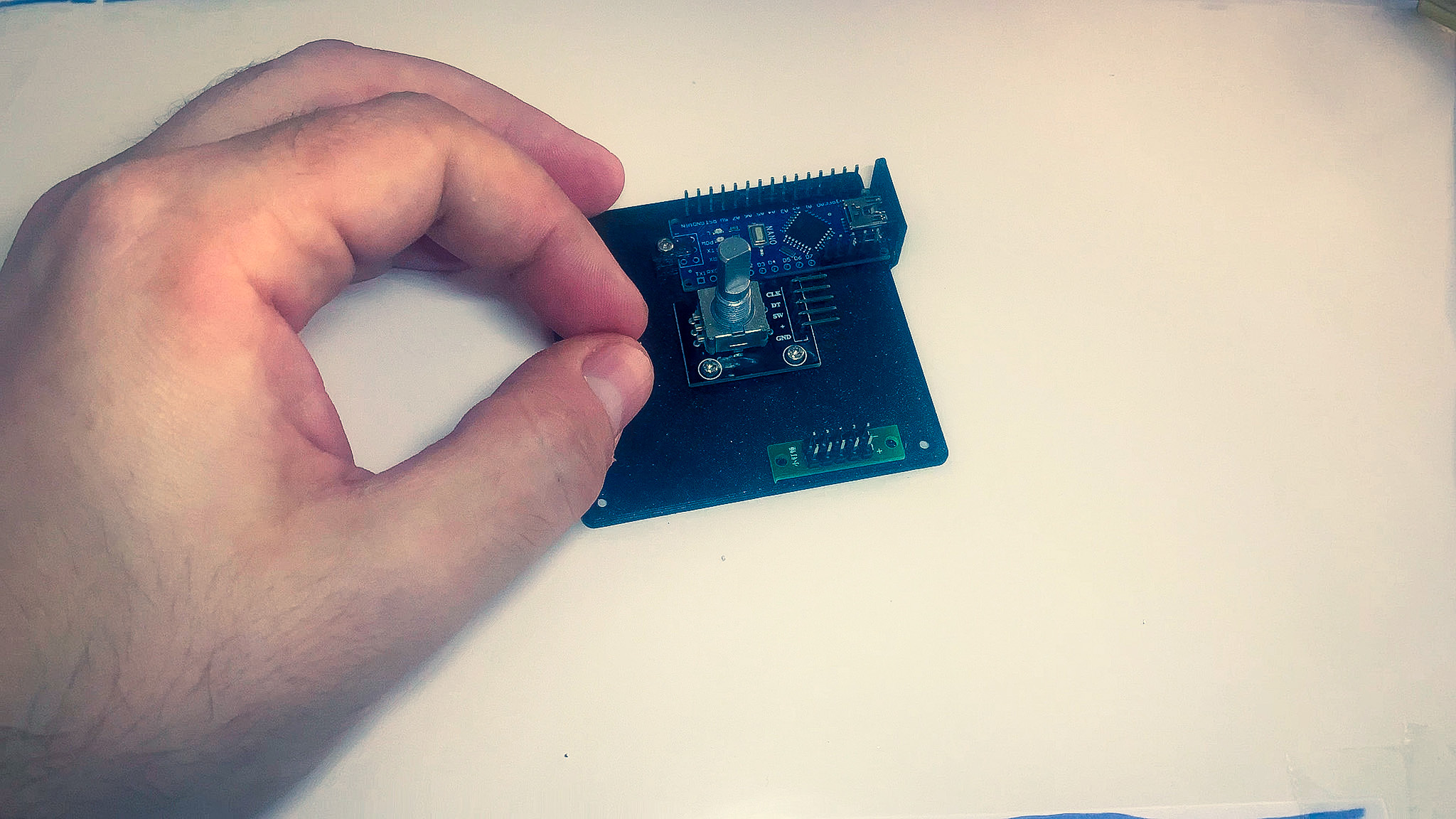
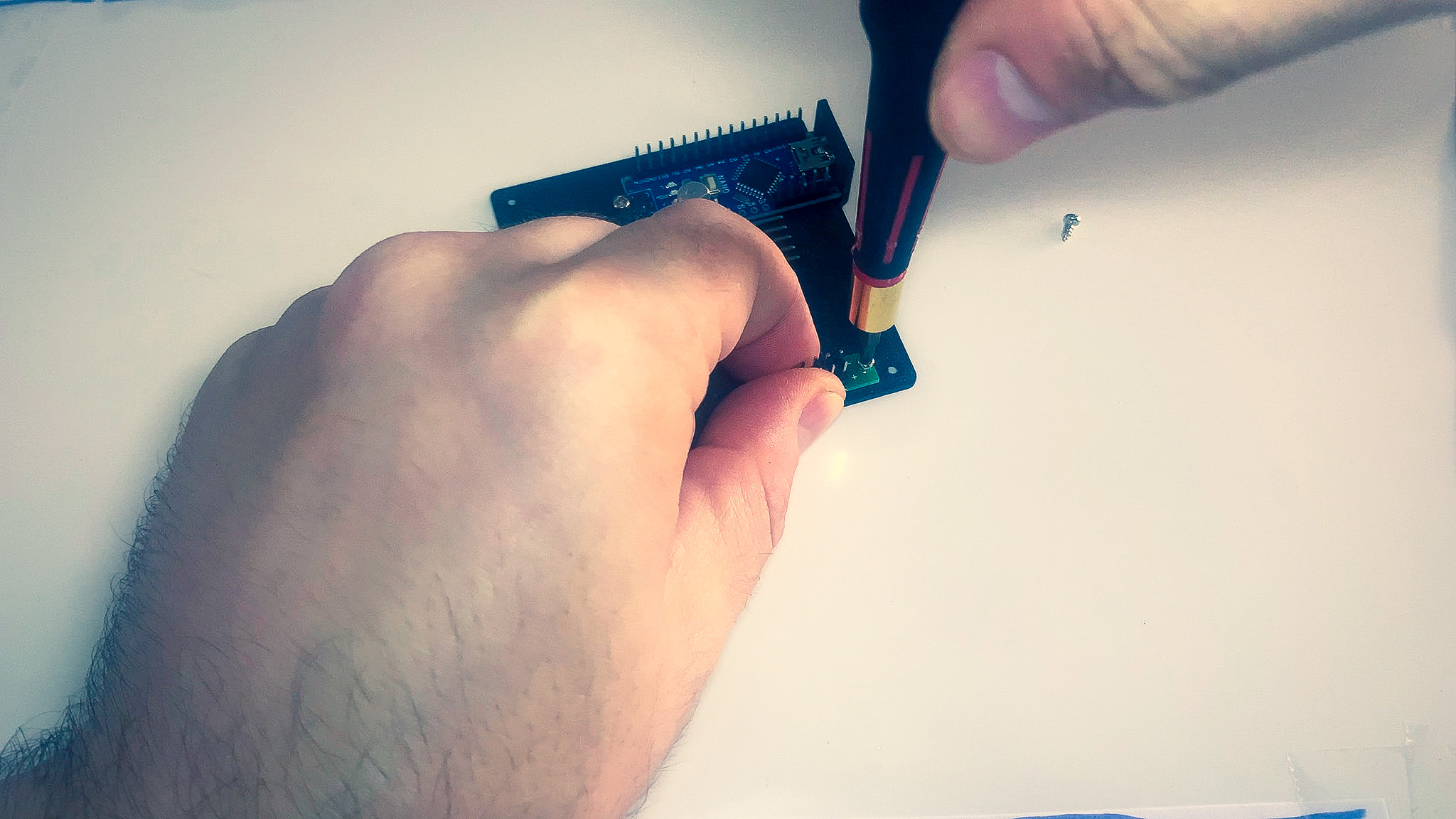
4. Power bus
- Grab the power-bus and the bottom part of the enclosure.
- Place the power-bus on the right hand side, lining up the holes.
- Secure it in place using the screws.
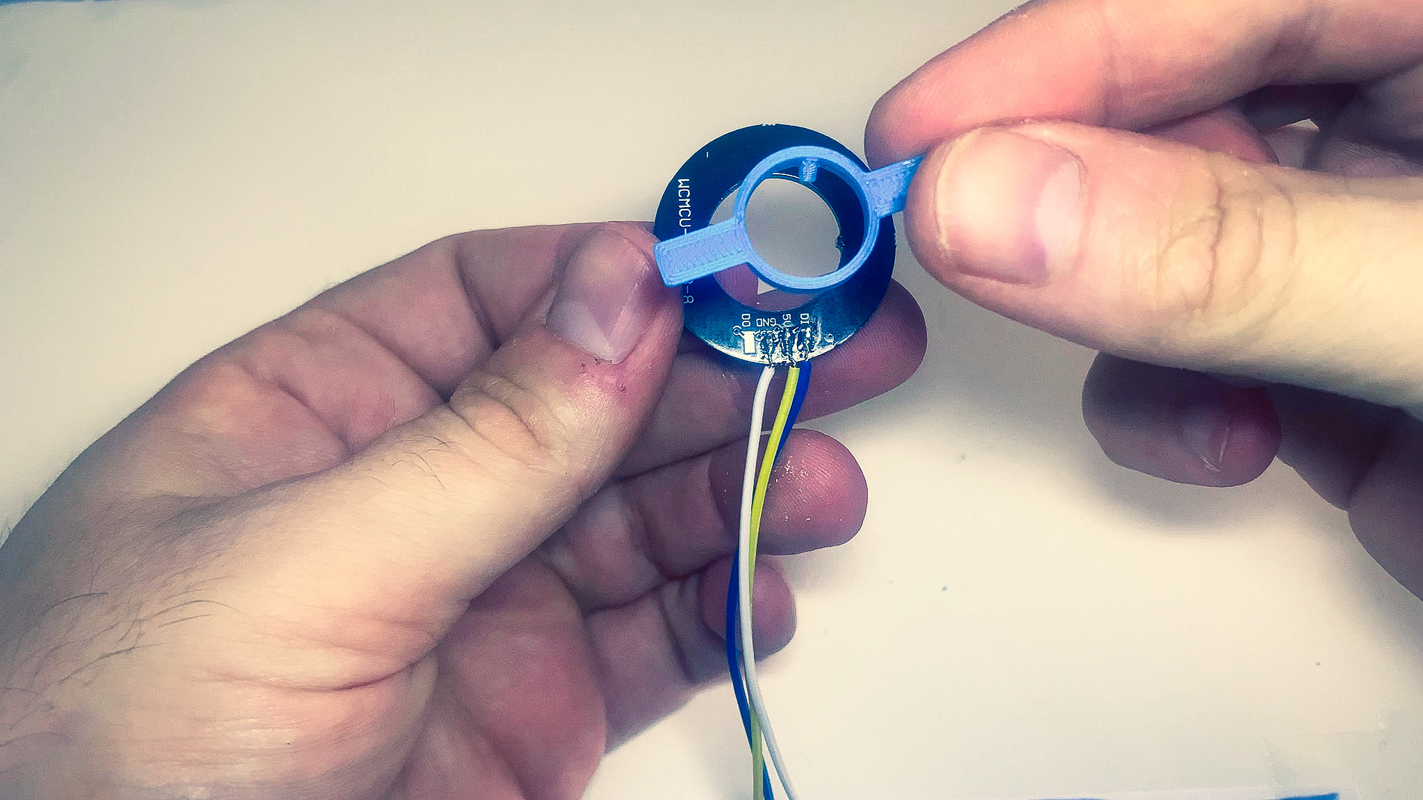
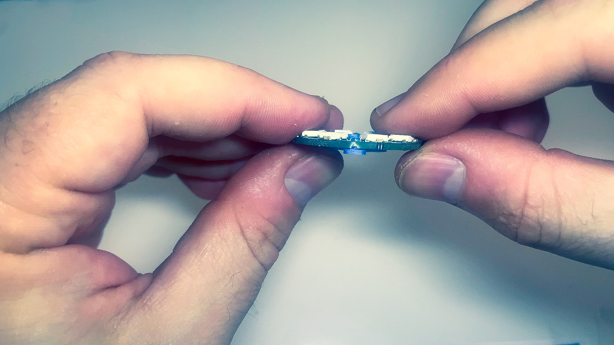
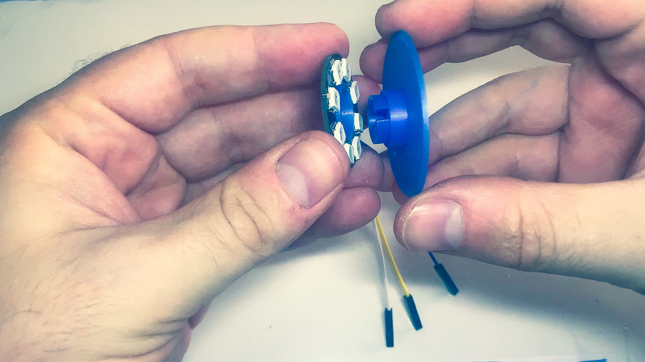
5. LED Ring (Optional)
The fit of the parts is designed to be very tight. Some sanding of the PCB holes may be required.
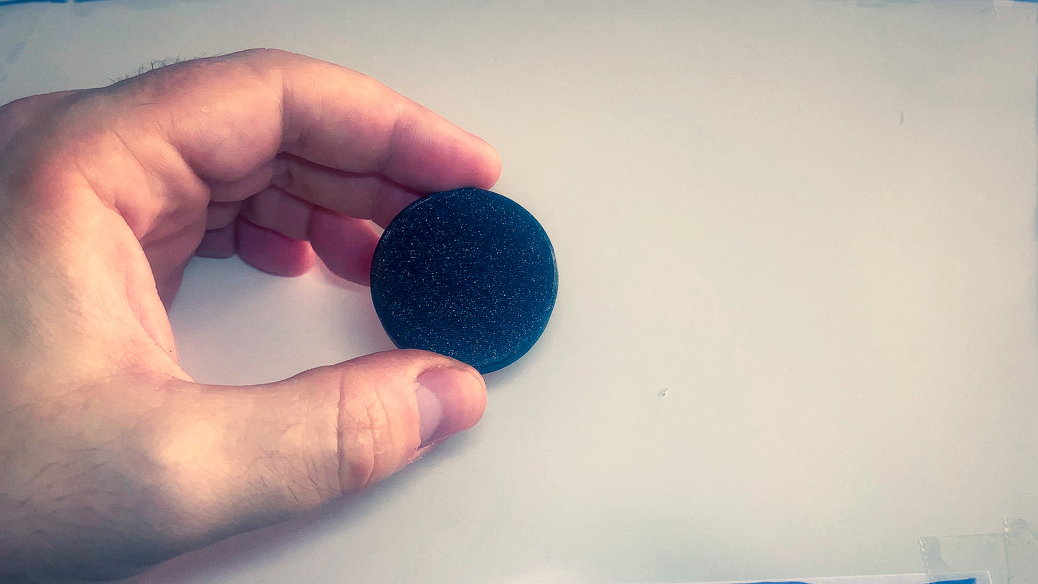
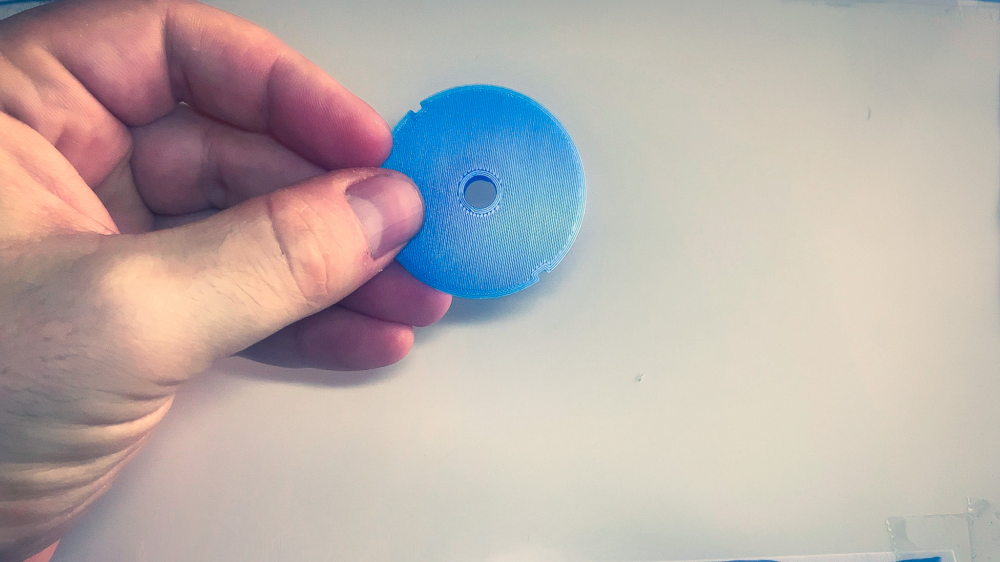
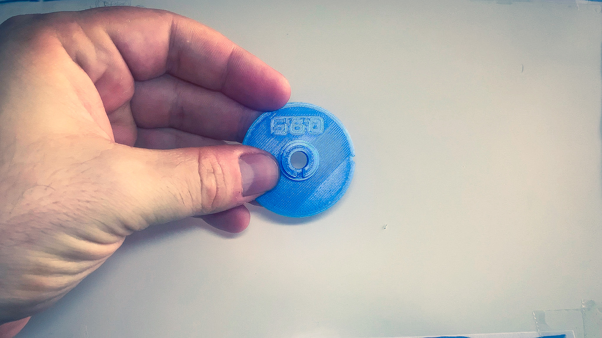
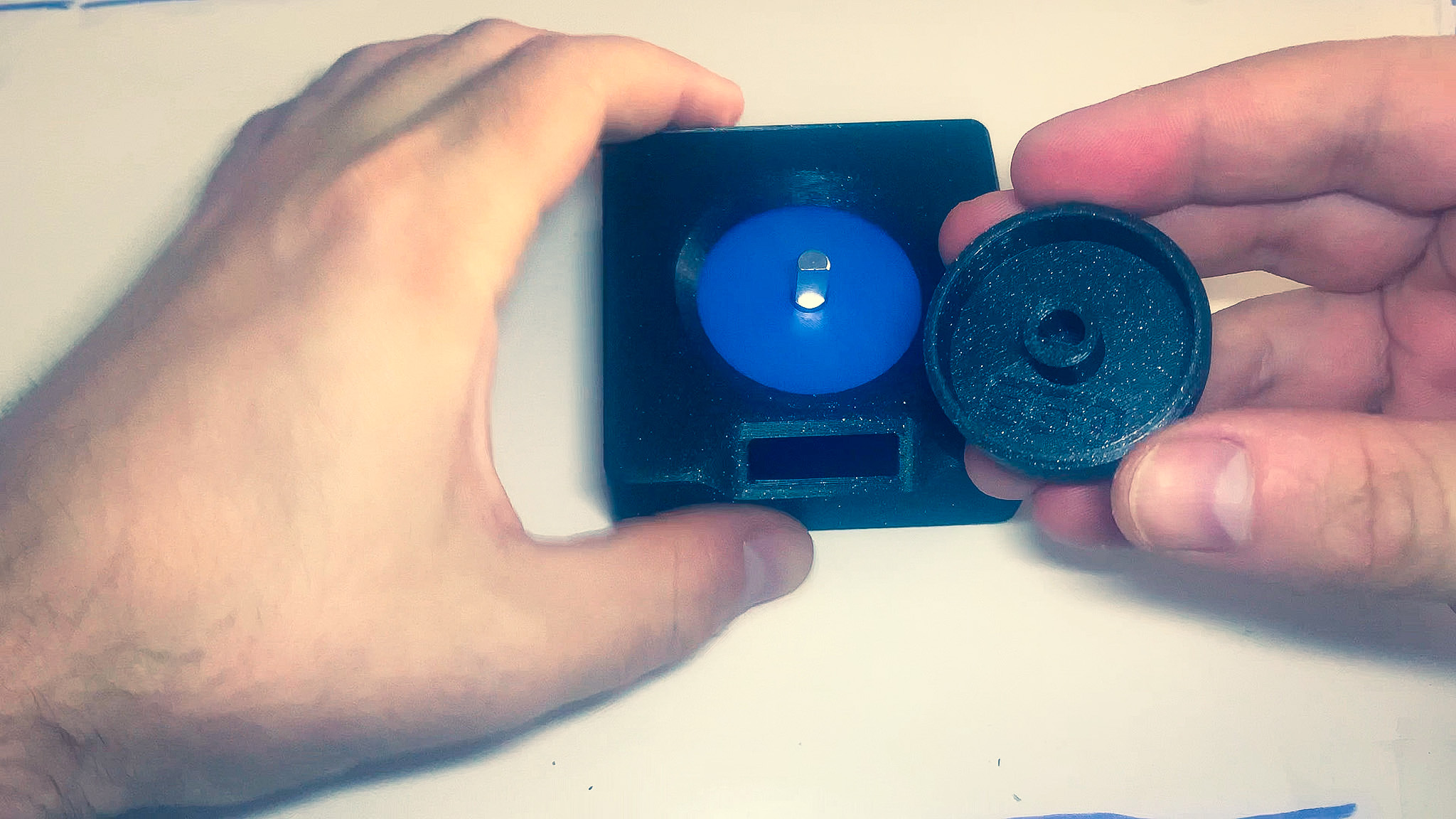
- Grab the ring holder 3D printed part.
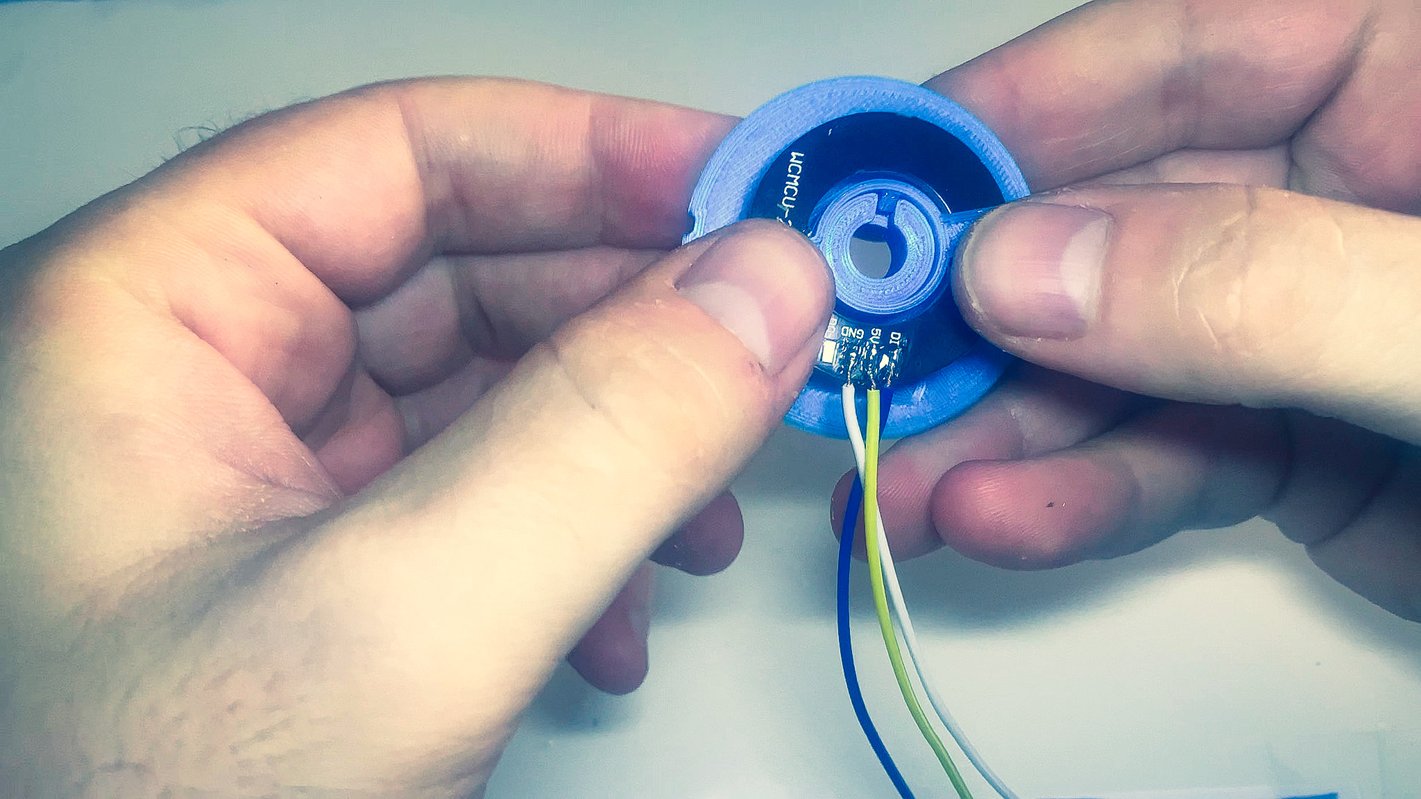
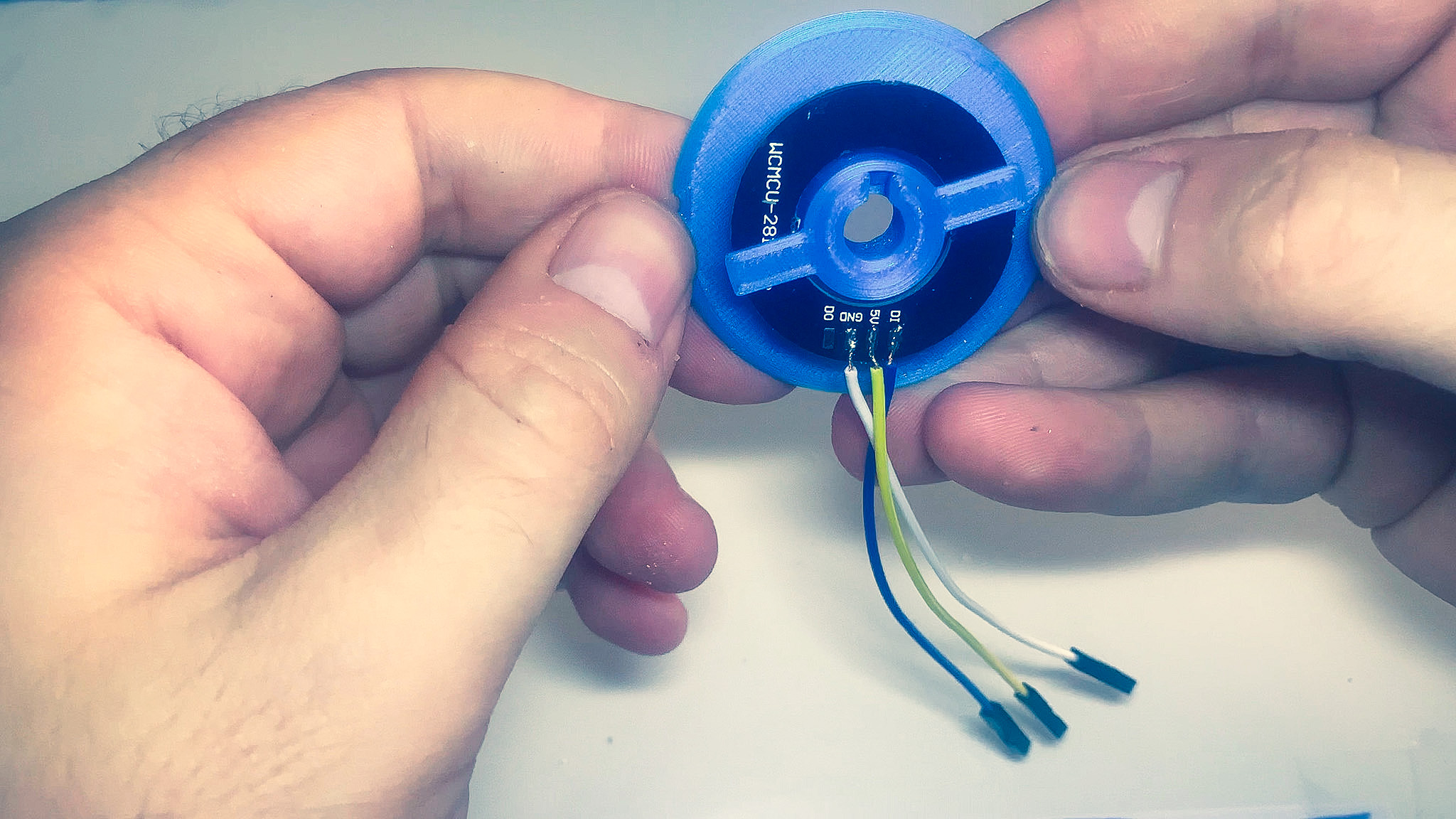
- Line up the pegs with the holes of the PCB, making sure that the notch in the holder is facing away from the wires.
- Apply some pressure to insert the pegs into the holes until it sits flush.
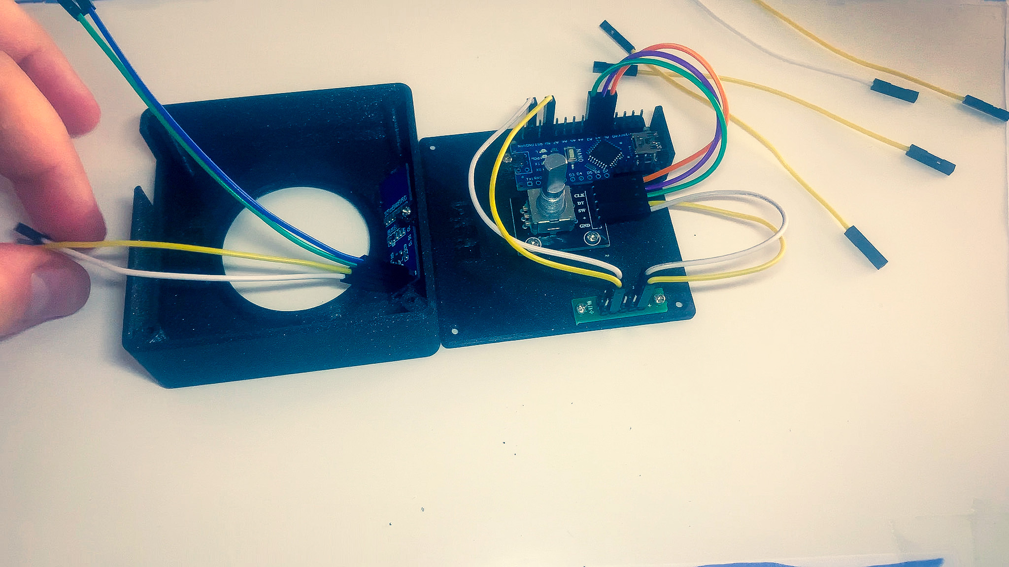
Wiring
Connecting wires incorrectly will destroy electronic components.
MCU Wiring
Use the table below to connect the wires between the MCU and the power bus.
| MCU | Power bus |
|---|---|
| GND | - |
| 5V | + |
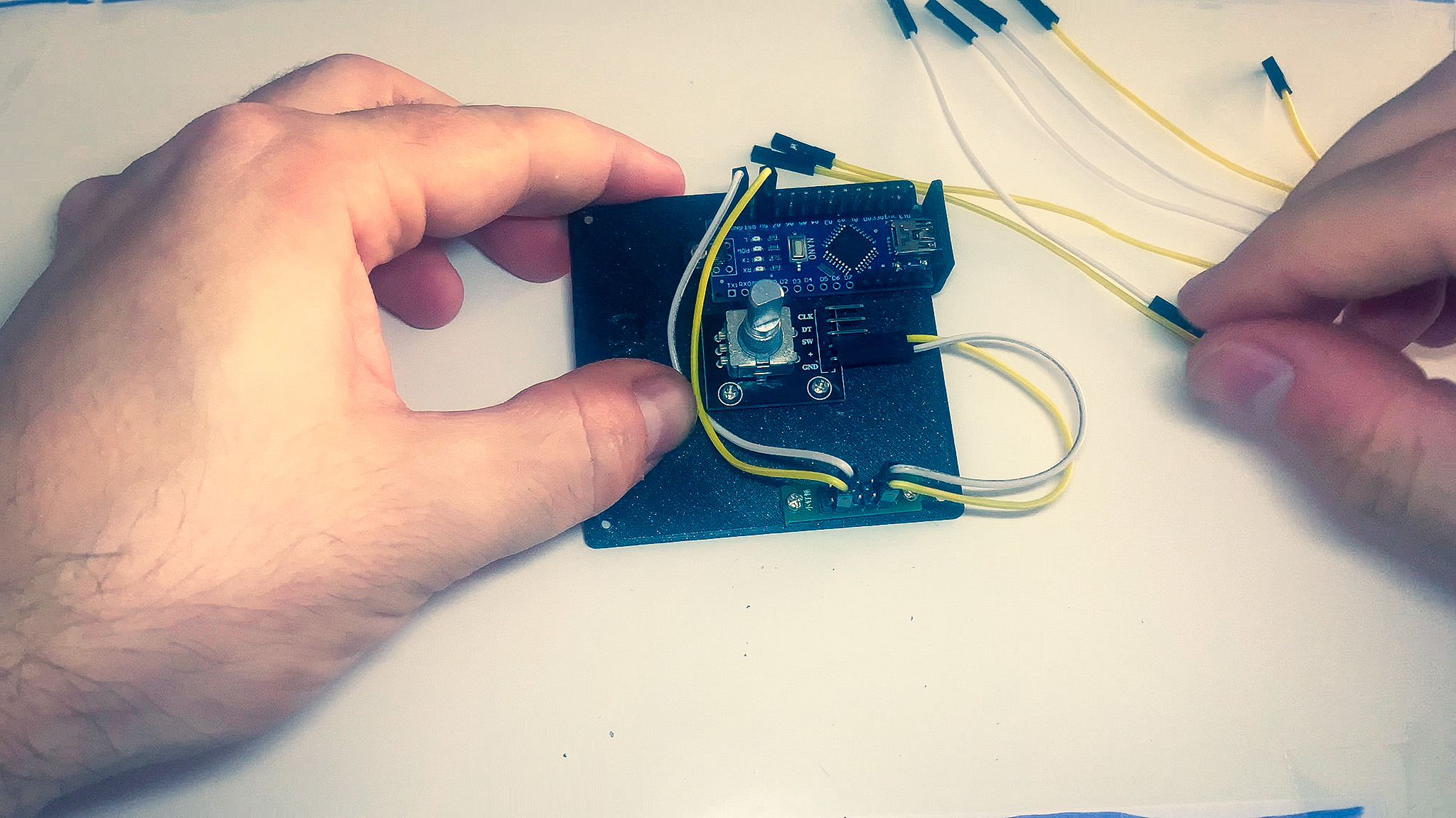
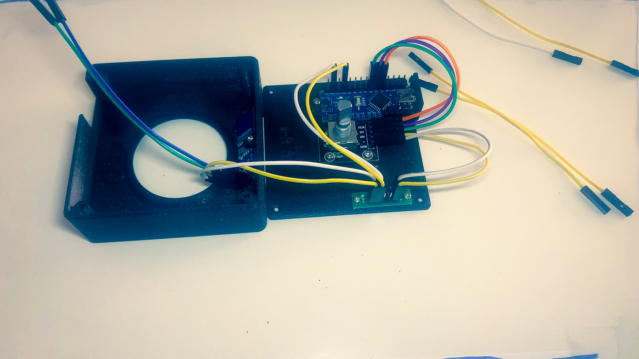
Rotary encoder
Use the table below to connect the wires between the MCU, rotary encoder and power bus.
| Rotary encoder | Power bus | MCU |
|---|---|---|
| GND | - | |
| + | + | |
| SW | A3 | |
| DT | A2 | |
| CLK | A1 |

Display
Use the table below to connect the wires between the MCU, display and power bus. The pins of the display are numbered from top to bottom.
| Display | Power bus | MCU |
|---|---|---|
| (1) GND | - | |
| (2) VCC | + | |
| (3) SCK | A5 | |
| (4) SDA | A4 |
LED Ring Wiring (Optional)
Use the table below to connect the wires between the LED ring, MCU and power bus. The pins of the display are numbered from top to bottom.
| LED Ring | Power bus | MCU |
|---|---|---|
| GND | - | |
| VCC | + | |
| DI | D12 |
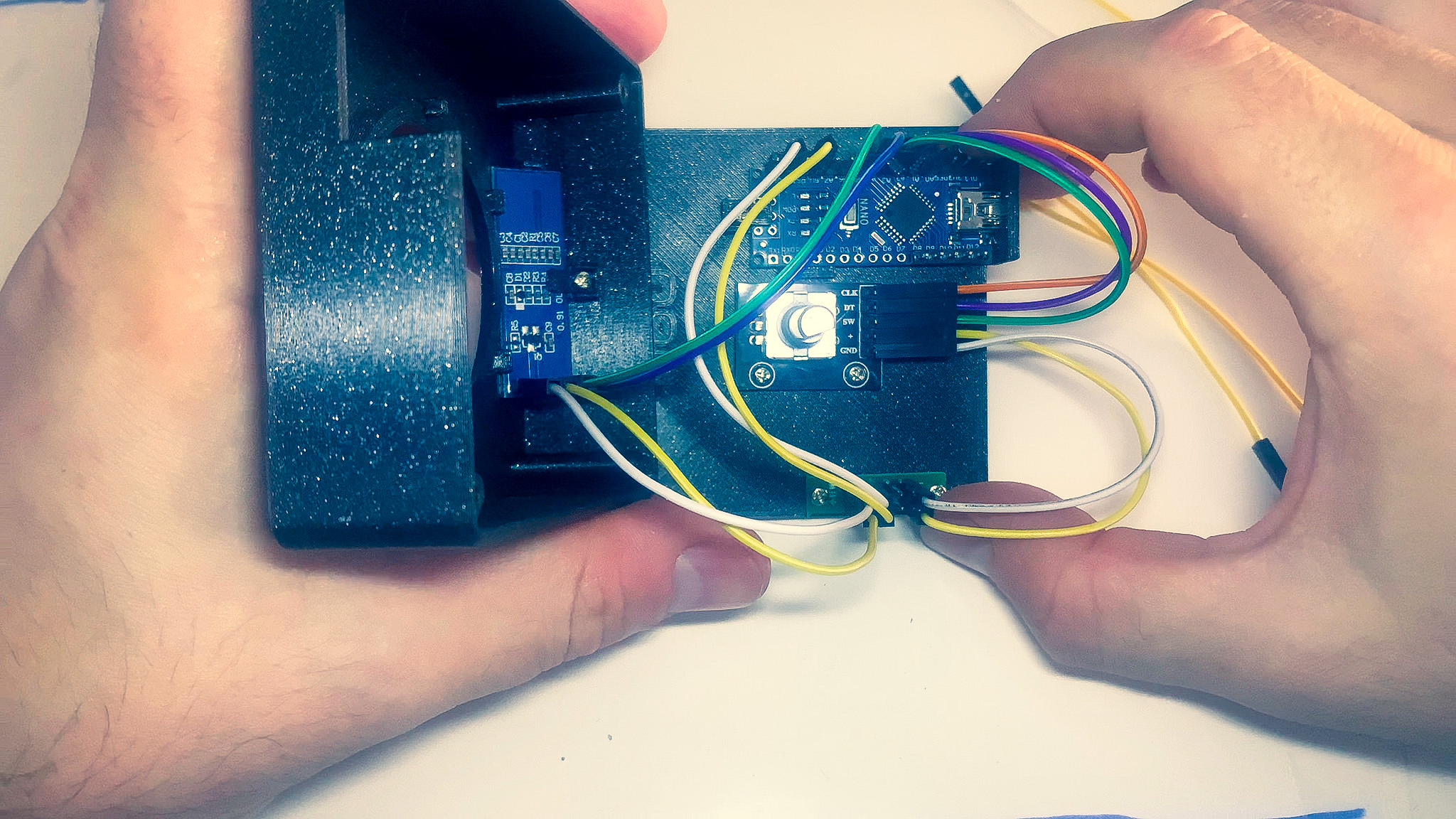
Assembly
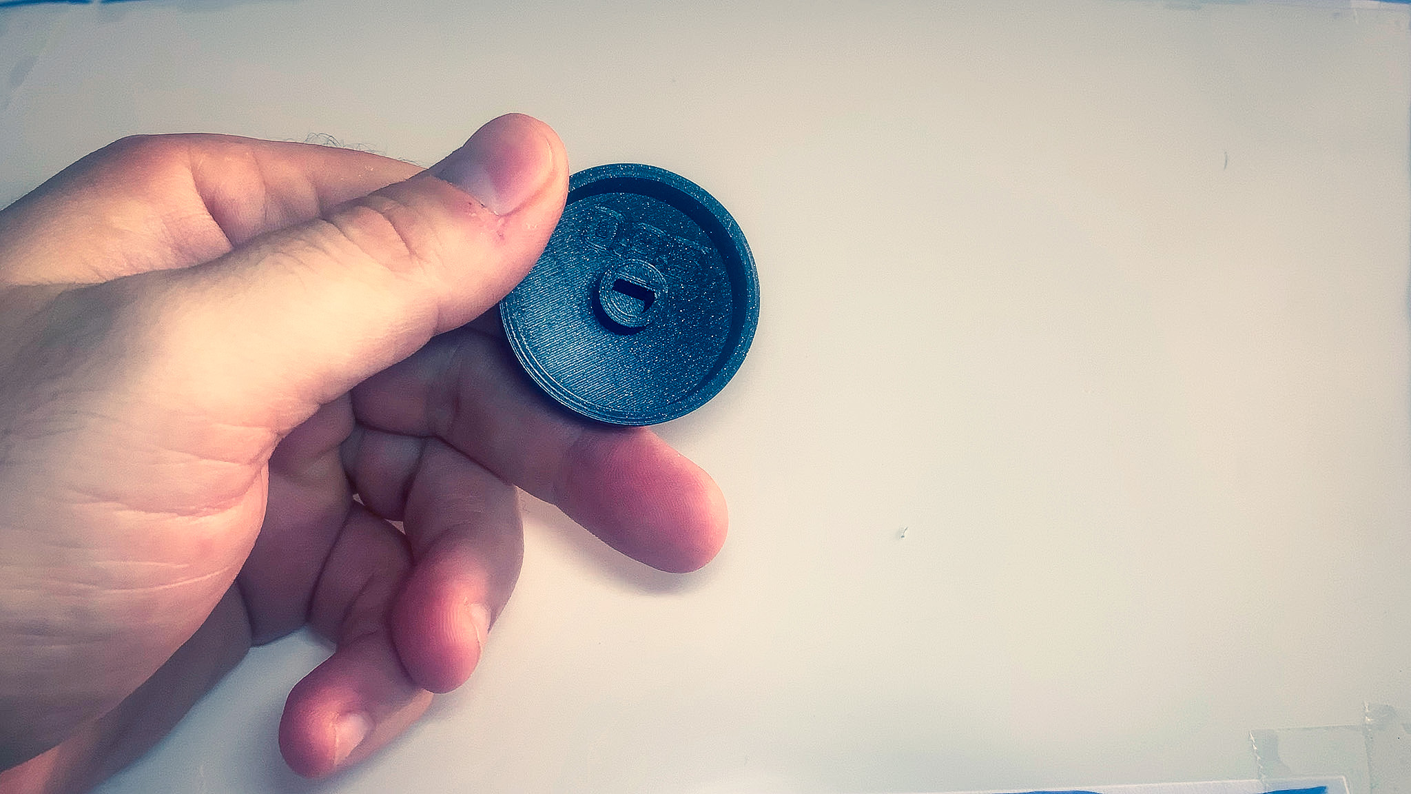
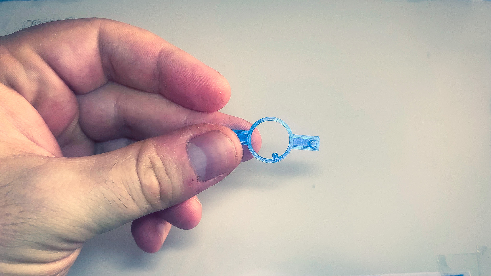
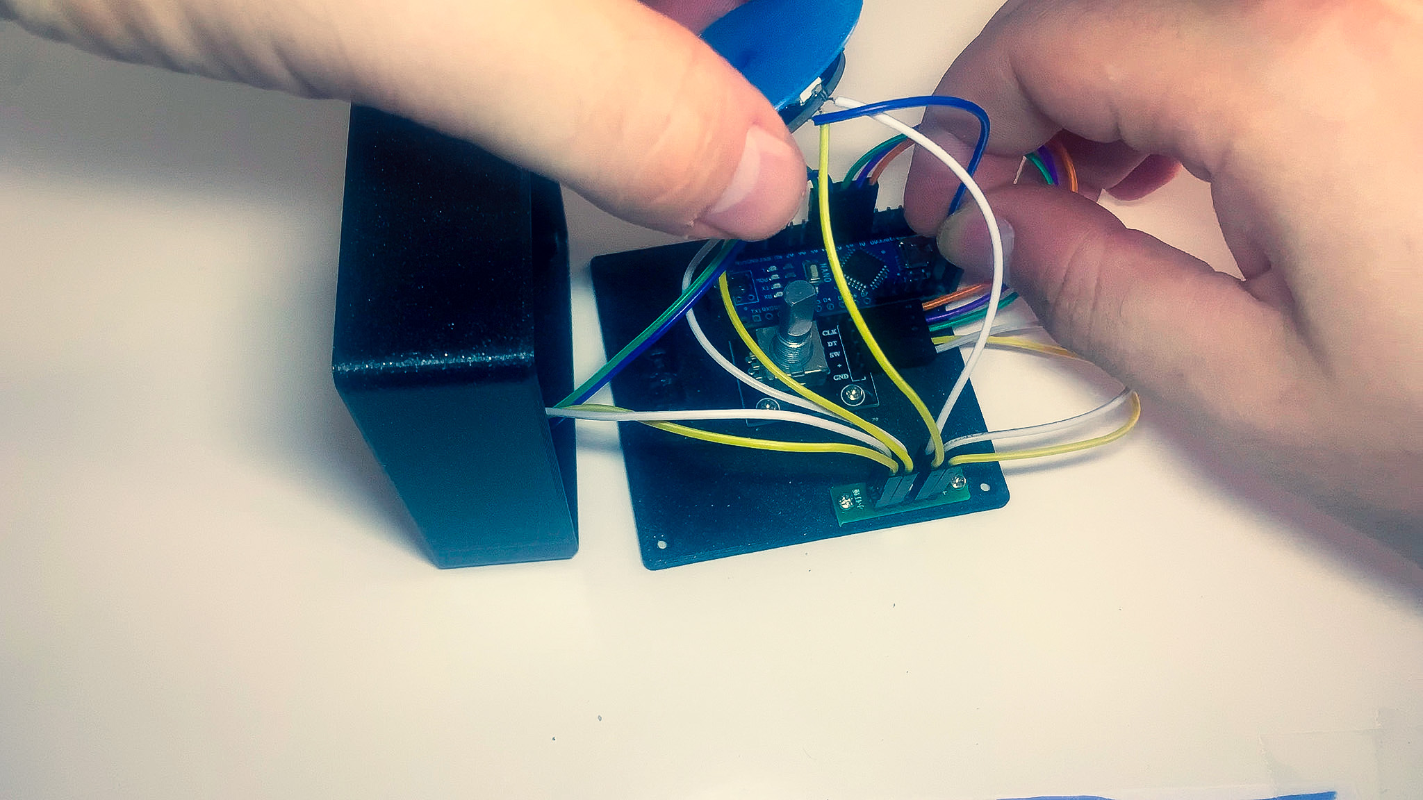
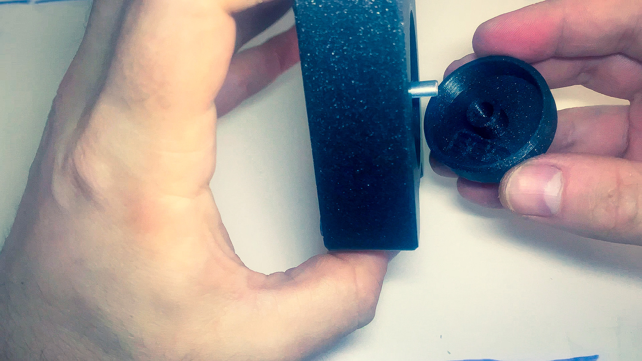
- Pass the shaft of the rotary encoder through the ring. Make sure that the little tab on the front of the encoder lines up with the notch on the bottom side of the ring and that it sits flush.
- Pre-bend and organize the wires so they are out of the way.
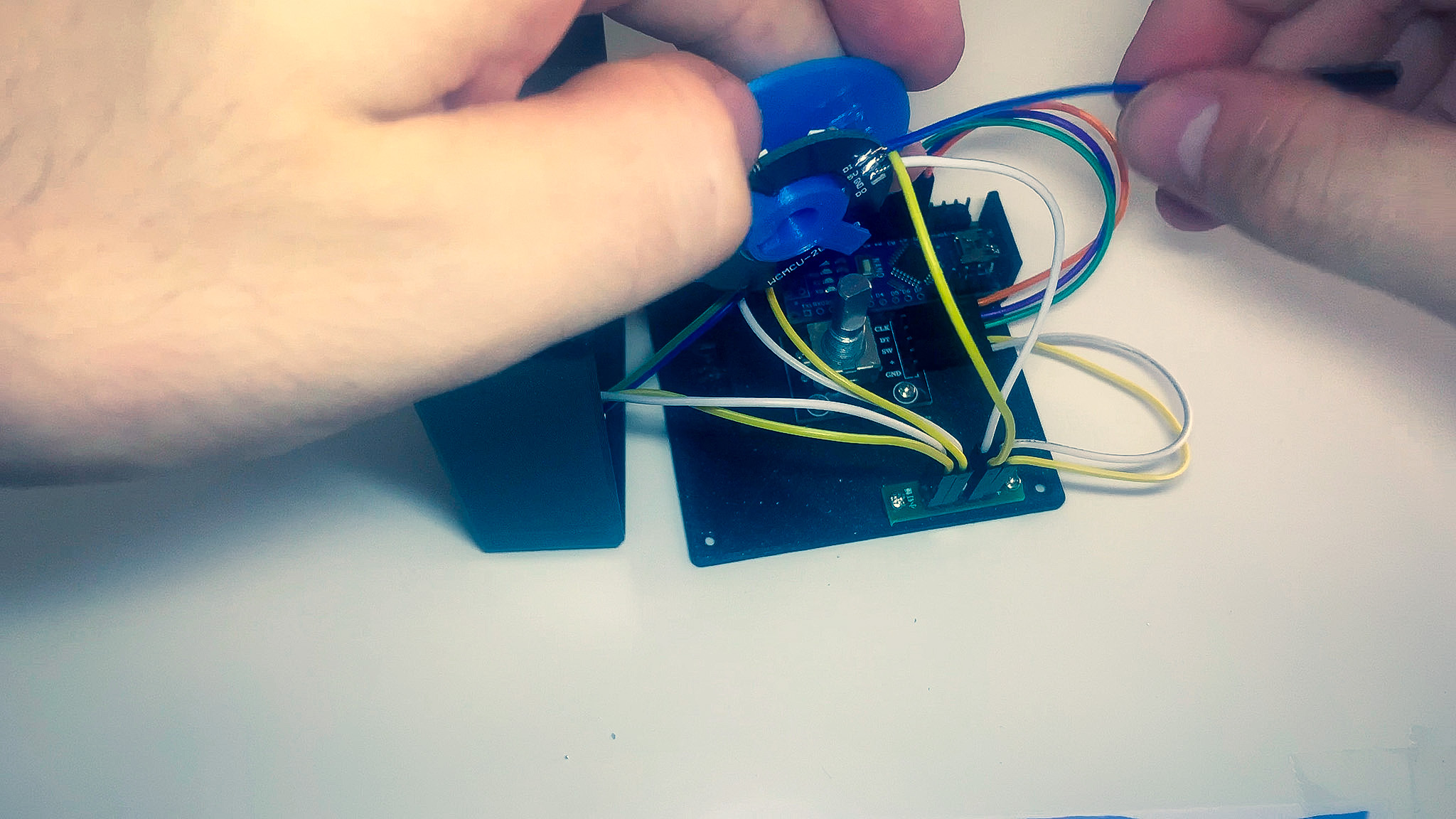
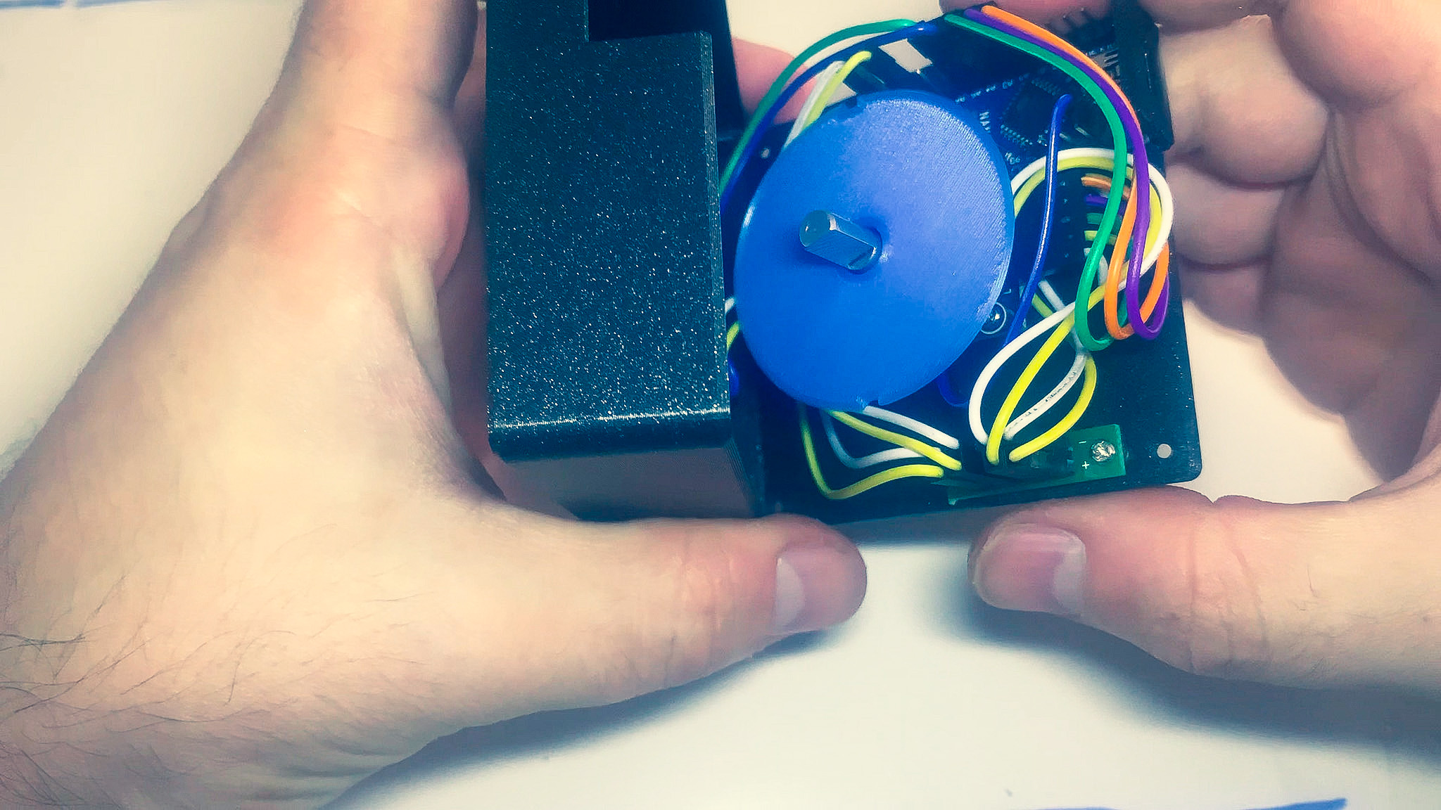
- Bring the top and bottom parts together until they snap in place.
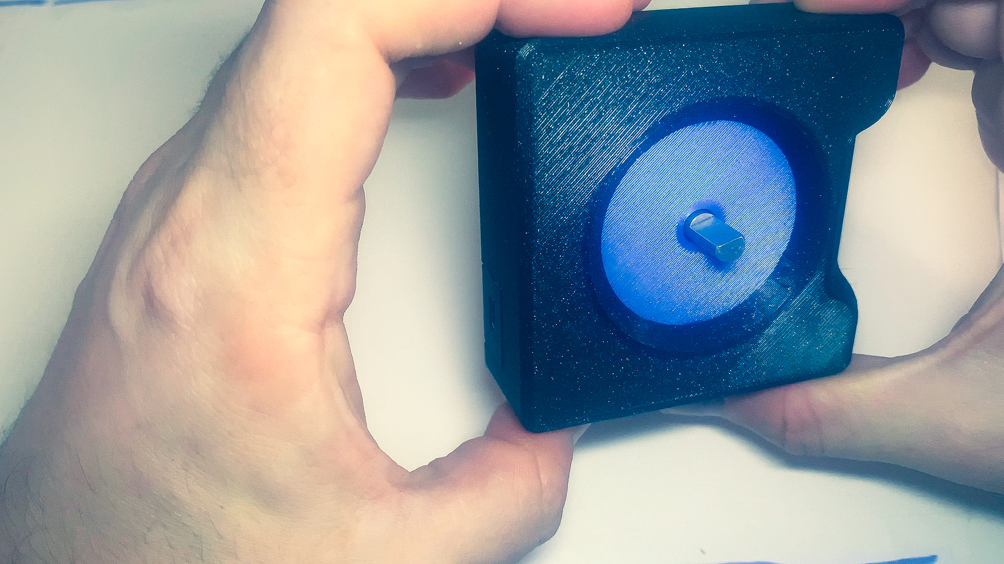
- Take a look at the ring from the top and make sure it sits flush with the top part of the enclosure. If needed, push on the bottom part of the enclosure until it fits in place.
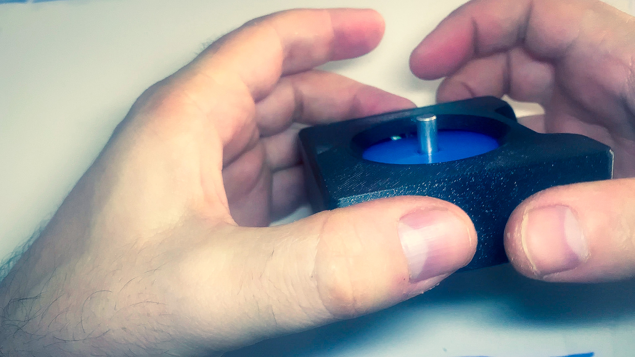
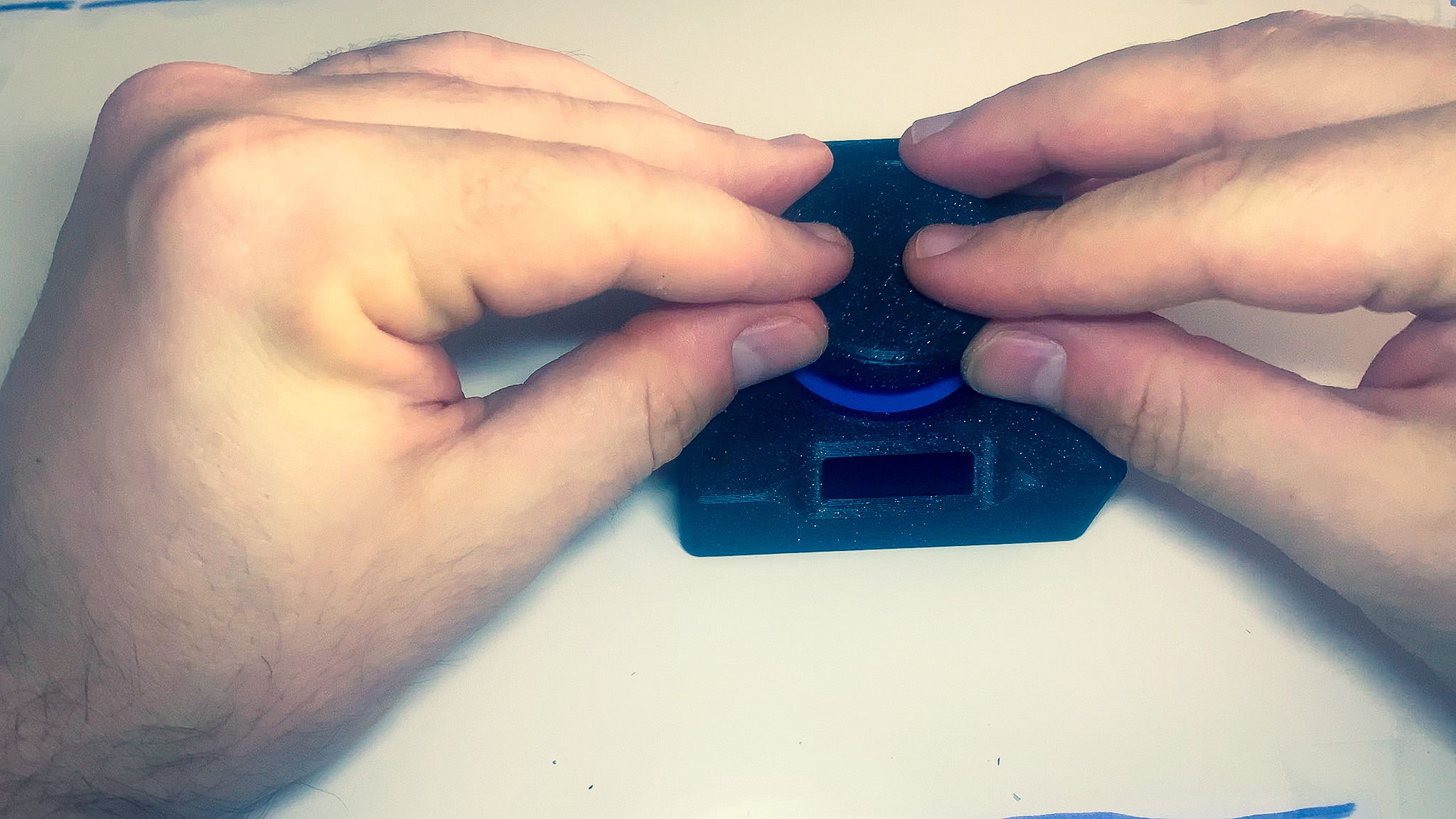
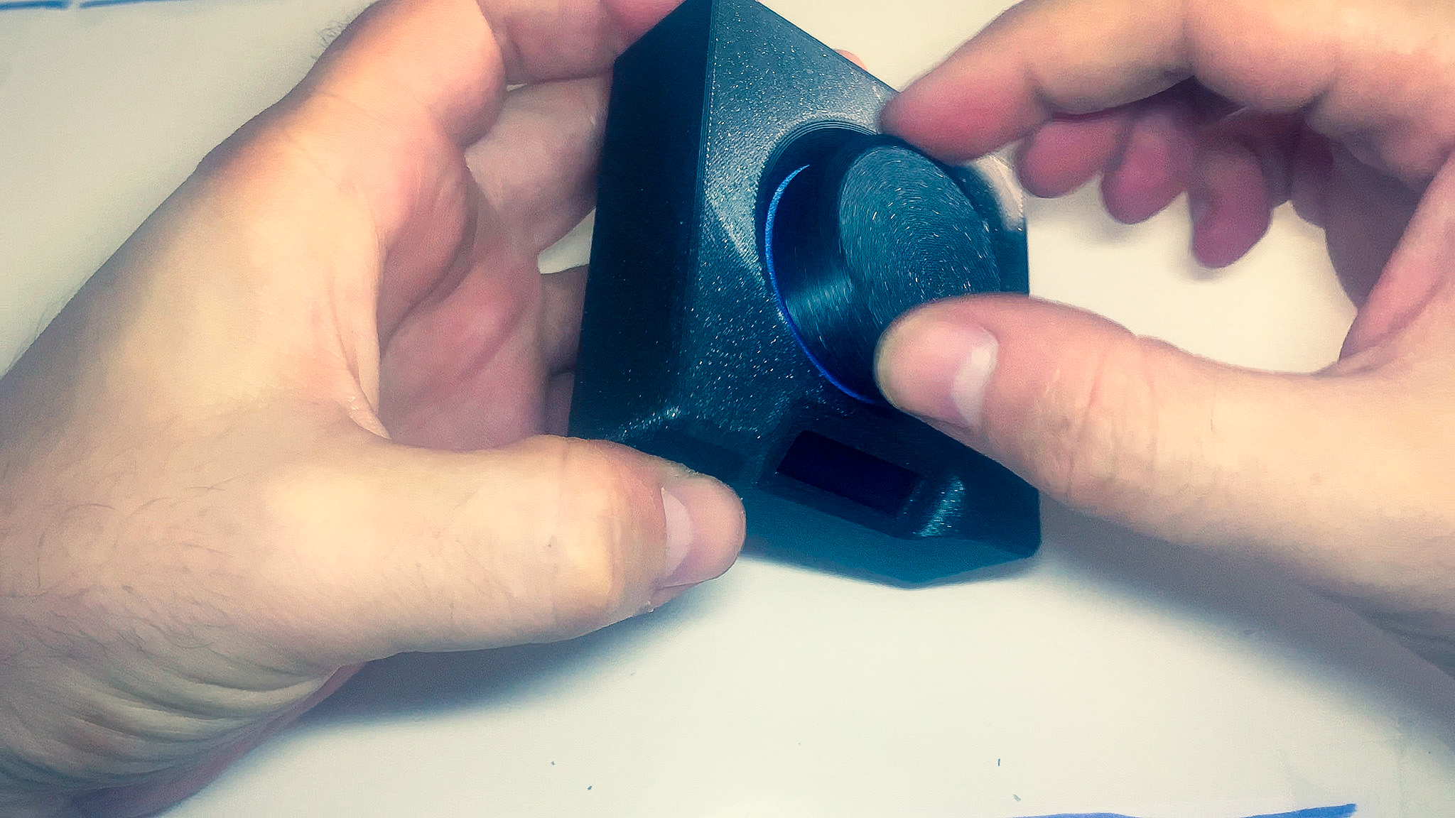
- Slide the knob on the shaft of the rotary encoder.
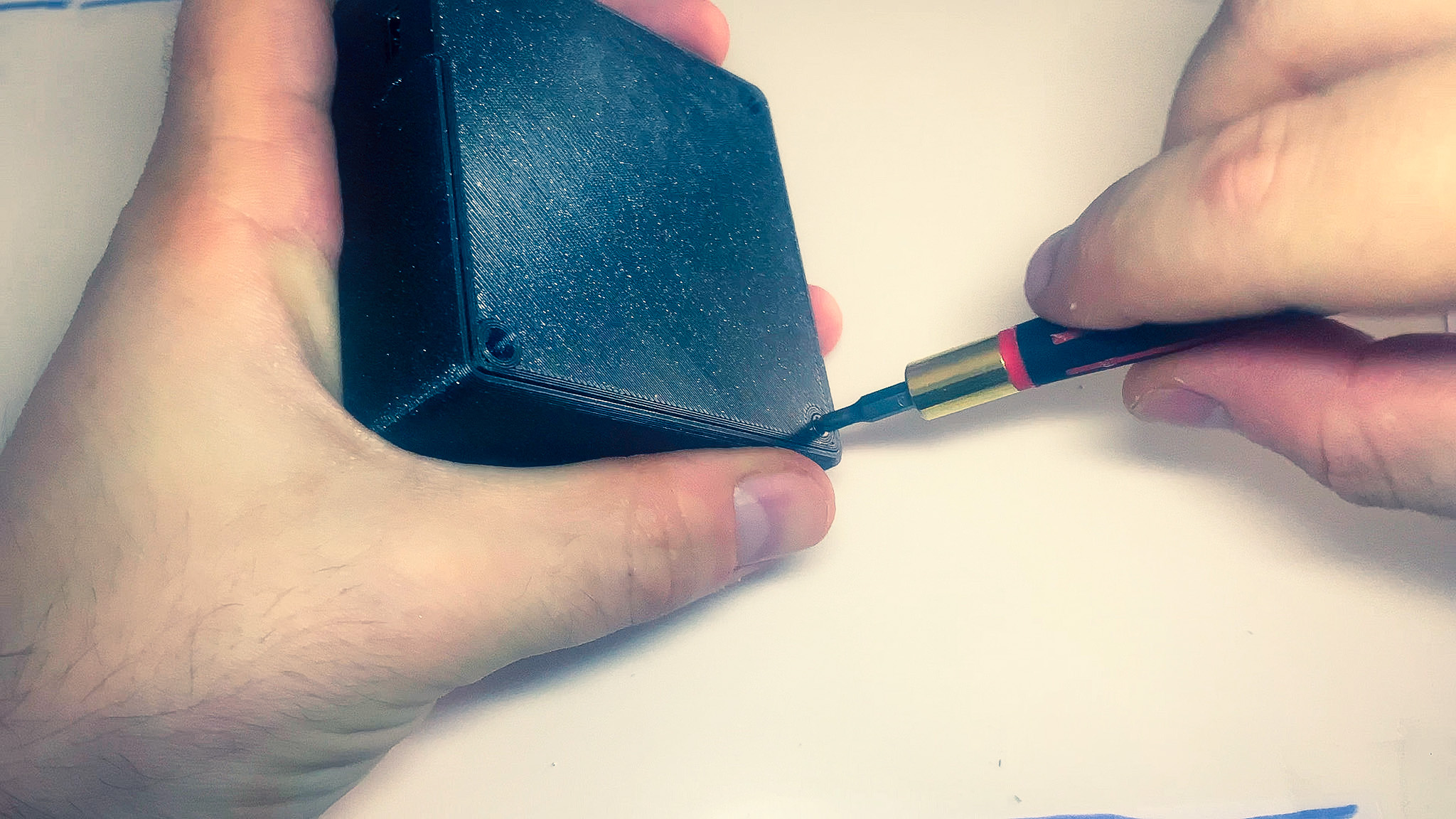
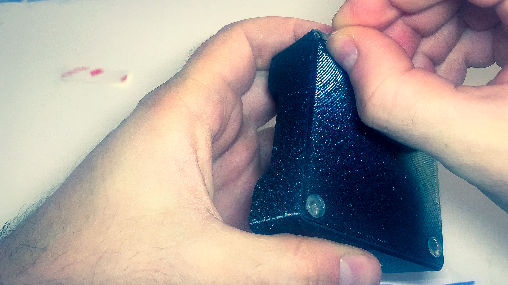
- Turn it upside down and use the 4 countersink screws to secure the two halves together.
- Place the silicon-bumpers on top of the the screws.
Congratulations
Congratulations you have completed the build!
You now have your very own Maxmix controller. Go to the install section and follow the instructions to get the software setup.